TM-9-2920-242-35 - Page 44 of 110
c. Assembly of Solenoid Plunger and Lever.
Refer to figure 31 and install solenoid plunger
and lever in lever housing.
33. ASSEMBLY
OF COMMUTATOR END
PLATE ASSEMBLY
a. Assembly
of Brush Holder Assembly.
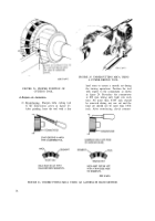
Refer to figure 11, step 3 and assemble the
brush holder assembly as follows:
(1)
(2)
(3)
(4)
b. Assembly of Lever Housing. Refer to fig-
ure 14 and assemble the lever housing as fol-
lows:
(1)
(2)
(3)
Install sleeve bearing (G) in lever hous-
ing (F). Ream sleeve bearing bore to
limits specified in wear limits (par.
41c).
Saturate wick (A) and felt plug (C) with
oil (OE). Apply sealer to expansion plug
seat. Install wick (A), felt plug (C), and
expansion plug (D). Fill reservoir with
oil (OE) and install pipe plug (B).
Apply sealer to oil seal counterbore
and install new oil seal (E).
(5)
Place insulated brush connection plate
(J), brush insulation plate (H), and ter-
minal plate (G) together. Install two
nonmetallic washers (K) in each of two
adjacent large holes in terminal plate
(G).
Install brush holder plate insulation (L),
insulated brush spacer plate (M), and
brush holder (E). Secure with a No. 10-
32 by 21/32-inch fillister head screw (S)
and No. 10 lock washer (R).
Install two helical torsion springs (Q)
and a No. 10 lock washer (P) on insu-
lated brush holder screw (2 inches lg)
(T) and install screw.
Install remaining insulated brush holder
following same procedure.
Install grounded brush spacer plate (F)
and brush holder (E) at top of terminal
plate (G). Secure with No. 10-32 by 3/8-
inch long fillister head screw (U) and a
No. 10 lock washer (B).
(6)
(7)
(8)
Install two brush springs (C) and a No.
10 lock washer (D) on grounded brush
holder screw (1-43/64-inch lg) (A) and
install screw.
Install remaining grounded brush holder
following same procedure.
Check for grounded brush holder. Touch
one probe of test lamp to terminal plate,
and the other probe to the insulated
brush holder. If the test lamp lights, a
ground is indicated. Disassemble and
replace defective parts if a ground is
evident.
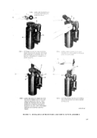
b. Assembly of Commutator End Plate. Refer
to figure 10 and assemble the commutator end
plate as follows:
(1)
(2)
(3)
(4)
(5)
(6)
(7)
Install a new bearing (N, step 4) in
commutator end plate (A). Ream sleeve
bearing bore to limits specified in wear
limits (par. 41e).
Saturate wick (R, step 4) and felt plug
(T) with oil (OE).
Apply sealer to expansion plug seat.
Install wick (R, step 4), felt plug (T),
and expansion plug (S).
Fill reservoir with oil and install pipe
plug (Q, step 4).
Install 0.516-inch ID nonmetallic washer
(H, step 3) and preformed packing (G)
on terminal stud of brush holder assem-
bly (J) .
Install brush holder assembly (J) in
commutator end plate (A) and secure
with three No. 8 by 1/2-inch pan head
screws (M), lock washers (L), and flat
washer (K).
Install bushing (F, step 3), terminal
stud insulator (E), 0.520-inch ID flat
washer (D), 1/2-inch lock washer (C),
and 1/2- inch, 0.310-inch thick hex nut
(B).
34. ASSEMBLY OF DRIVE HOUSING
Refer to figure 9 and assemble drive housing
as follows:
35
Back to Top


