TM-9-2920-242-35 - Page 45 of 110
a. Install new sleeve bearing (G) in drive
housing (B). Ream sleeve bearing bore to limits
specified in wear limits (par. 41e) and drill oil
hole.
b. Saturate wick (G), and felt plug (D) with
oil (OE).
c. Apply sealer to expansion plug seat. In-
stall wick (G), felt plug (D), and expansion plug
(E).
d . Fill reservoir with oil and install pipe
plugs (H and F).
e. Install rubber plugs (A) in housing (B).
35. ASSEMBLY OF STARTER ASSEMBLY
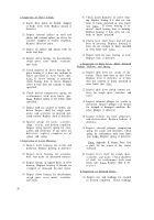
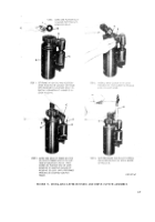
a. Installation of Solenoid Relay. Refer to
figure
32
and install solenoid relay on frame
assembly.
b. Installation of Lever Housing and Drive
Clutch. Refer to figure 33 and install lever hous-
ing
drive
clutch.
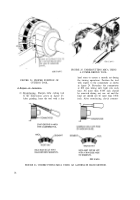
c. Installation of Commutator End Plate
Brushes and Armature. Refer to figure 34 and
install commutator end plate, brushes, and ar-
mature.
If new brushes are to be installed, cut
a strip of 2/0 sandpaper the width of the
commutator, and install on commutator
with sand side out, see step 1.
Install commutator end plate on arma-
ture. Lift brush springs using impro-
vised brush spring lifter (fig. 3) and
install brushes. Brushes must lie flat
against sandpaper on commutator to
obtain the desired brush seat contour.
Hold armature and carefully rotate com-
mutator end plate assembly in a clock-
wise direction three to five revolutions
to properly seat all brushes.
Lift brush springs and raise each brush
and inspect seat contour to determine
whether or not the sanding operation is
satisfactory. Refer to figure 35 for ex-
amples of satisfactory brush seats.
FIGURE 32. INSTALLING SOLENOID RELAY.
36
Back to Top


