TM-9-2920-242-35 - Page 49 of 110
(5)
(6)
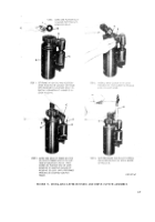
Mark location of brushes, and, remove
brushes from holders. Remove commu-
tator end plate from armature. Remove
sandpaper,
and
clean
armature,
brushes,
and commutator end plate.
Sanding dust can be removed using com-
pressed air.
Install commutator end plate, brushes,
armature, brush leads and terminal
lead following steps 2 through 6, fig-
ure 34.
Note. The armature shaft and splines
must be coated with grease (GL) before
installation. Coat all exposed metal of
starter lead and terminals with vinyl
latex or equivalent.
d . Installation of Drive Housing. Refer to
figure 36 and install drive housing.
36. ADJUSTING DRIVE CLUTCH PINION
CLEARANCE
a. Check and adjust pinion clearance as de-
scribed below. Refer to figure 37 for schematic
wiring diagram of starter and solenoid con-
nections.
(1)
(2)
Remove motor field coil connector from
the motor switch terminal stud.
Remove ground lead assembly connect-
ing motor solenoid terminal and starter
ground terminal stud.
FIGURE 37. STARTER WIRING DIAGRAM - SCHEMATIC.
40
Back to Top


