TM-9-2920-242-35 - Page 42 of 110
32. ASSEMBLY OF DRIVE CLUTCH AND
LEVER HOUSING
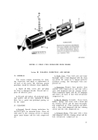
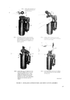
a. Assembly of Drive Clutch. Refer to fig-
ures 29 and 30 and assemble the drive clutch.
After clutch has been assembled, it must be
checked for slippage.
(1) With clutch held stationary, the pinion
must slip when 4000 pound-inches is
(2)
applied in direction of torque. Torque
is counterclockwise as viewed from
pinion end.
With clutch held stationary, twelve
pounds pressure must be required to
move pinion to “stop” position, with a
16 degree, 15 minute clockwise motion
viewing pinion end.
FIGURE 30. ASSEMBLING EXTERNAL PARTS OF DRIVE CLUTCH ASSEMBLY.
33
Back to Top

