TM-9-2920-242-35 - Page 33 of 110
f. Brushes. Clean brushes with a clean, dry
cloth only. Do not permit dry cleaning solvent
to contact the brushes.
26. INSPECTION
a. Inspection of Drive Housing.
(1)
(2)
(3)
(4)
(5)
(6)
Inspect drive housing for cracks and
distortion. Replace housing if defective.
Inspect housing for scratches, burs, and
nicks on machined surfaces. Repair as
necessary (par. 27a).
—
Inspect threads in tapped holes in hous-
ing for damaged threads. Replace hous-
ing if threads are stripped or damaged
beyond repair.
Inspect sleeve bearing for discoloration,
rough spots, score marks, scratches,
and nicks.
Check inside diameter of sleeve bearing.
Replace bearing if it does not conform
to limits specified in wear limits (par.
41e) . If sleeve bearing is removed,
check bearing bore in housing. Replace
housing if bore does not conform to
limits specified in wear limit (par. 41e).
Note. Appendix II, Repair Parts, lists
a sleeve bearing set to be used in re-
pair of the starter.
Inspect wick for tears, fraying, or wear.
Replace wick if defective.
b. Inspection of Commutator End Plate.
(1)
(2)
(3)
(4)
Inspect commutator end plate for cracks
and distortion. Replace plate if defec-
tive.
Inspect end plate for scratches, burs,
and nicks on machined surfaces.
Inspect threads in tapped holes of end
plate for damage. Replace end plate if
threads are stripped or damaged beyond
repair.
Inspect sleeve bearing for discoloration,
rough spots, score marks, scratches;
and nicks.
(5)
(6)
Check diameter of sleeve bearing. Re-
place bearing if it does not conform to
limits specified in wear limits (par.
41e) . If sleeve bearing is removed,
check bearing bore in end plate. Replace
end plate if bore does not comform to
limits specified in wear limits (par.
41e).
—
Note. Appendix II, Repair Parts, lists
a sleeve bearing set to be used in re-
pair of the starter.
Inspect wick for tears, fraying, or wear.
Replace wick if defective.
c. Inspection of Brush Holder Assembly and
Brushes.
(1)
(2)
(3)
Check insulation, spacers, plates, and
brush holders for distortion and cracks.
Replace defective parts.
Check brushes and springs for cracks
or breaks. Check brush spring tension
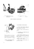
(step 1, fig. 10) for conformity to wear
limits (par. 41a) . If any brushes are
defective, replace entire set with brush
kit. Replace springs if they do not con-
form to wear limits.
Inspect terminal plate stud for damaged
threads.
d. Inspection of Armature.
—
(1)
(2)
(3)
Check armature shaft and commutator
for conformity to wear limits (par. 41e).
Replace the armature if worn beyond
limits specified.
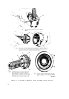
Inspect armature for grounds with a test
light by touching one of the test probes
to the armature core and the other probe
to one of the commutator bar risers
(fig. 20). Test all commutator bars in
this manner. If the test light glows, the
armature is grounded and must be re-
placed.
Inspect armature for short circuits
using a growler fixture. Place the ar-
mature in the growler as shown in fig-
ure 21. Hold a thin strip of steel, such
as a hacksaw blade about 1/32 inch
away from armature. While holding the
steel strip in position, rotate the arma-
24
Back to Top

