TM-9-6015 - Page 21 of 54
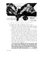
easily on the pin (fig. 7) and the thumb nut locks firmly
into the bracket. The thumb nut should thread easily on the
sc rew tread which should be coated with lubricant and free of
corrosion. grit and dirt.
(4)
Forms and reports.
Authorized forms and reports for tech-
nical inspections are prescribed in TM 9-1100. For addi-
tional authorized forms and reports for field and depot main-
tenance, refer to paragraph 3.
(5)
Identification.
Inspect
lettering
engraved on case to see
that
it is clearly defined and easily read.
(6)
Paint and brush finish.
Inspect for bare spots or damaged finish
which expose base metal surfaces and lead to corrosion.
The
push fit between the reflector shade and case of the aiming
post light causes the paint on the case to be scraped off when
the reflector shade is removed.
This scraped off area and
other scrapes or scratches do not require a complete paint
refinishing of the light.
The area affected should be sanded
smooth with a fine grade No. 2 abrasive cloth and touched
up as required. Refer to TM 9-2851 for painting procedures.
(7)
Lubrication.
With the exception of the clamps on the
bracket, aiming post lights have no moving mechanical parts,
or parts subject to mechanical friction. Keep the thumbnut
or wing nut screw free of dirt and grit and lubricate the pins,
a
nd thumbnut and wing nut threads with a drop of light oil
applied once weekly.
(8)
Cracks.
Stamping and welds should be inspected for cracks
and breaks.
(9)
Spare parts and equipment.
Spare parts and equipment will
b
e checked against ORD 7 SNL F-205 for completeness.
(10)
Condition of optics.
Window and filter assemblies must be
free from scratches, pits, dirt, and chips as will interfere with
cleaning of their surfaces or which affect optical performance
of the aiming post light.
c. Inspection of Electrical Components
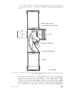
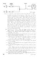
(figs. 4, 5, and 6).
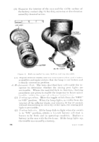
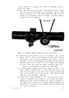
(1) Aiming post lights are equipped with only one control which
is a single pole, single throw toggle switch. This switch
should move easily, with a sharp click, from the “OFF” to
“ON” position.
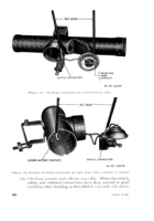
(2) Remove cover and cap assemblies and examine interior for
dirt, corrosion or acid action.
(3)
Examine
battery
cells
for
cracks
and
defects.
Cylindrical
insulating jackets must not be torn, discolored, or contain
foreign matter. Be sure not to use batteries on which the
service date limit, indicated on the jacket, has passed.
1 5
Back to Top

