TM-9-6015 - Page 29 of 54
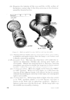
check condition of contacts and reflector assembly with a
6-volt test lamp.
(a)
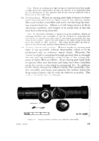
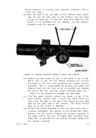
Place one lead of the test light on the reflector lamp contact
(fig. 15) and the other lead on the reflector. The test lamp
should
not
light up.
If the test lamp does light up, the
contact is not insulated from the reflector, and the reflector
assembly must be replaced.
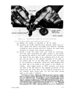
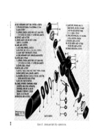
Figure 15. Testing insulation between contact and reflector.
(b )
(c )
(d )
TAGO 3108B
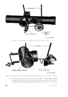
Remove the two screws (C, fig. 17 (for M14) C, fig. 19 (for
M41), and C, fig. 20 (for M43)) holding the contact
assembly to the case and withdraw this upper contact
assembly.
This is accomplished by pushing the switch and
reflector back into the case as far as possible and tapping
the end of the case until the contact assembly drops out.
Note.
It is not necessary to undolder the cable leads.
Test the upper battery contact (as shown on fig. 16 for
lower battery contact) with a 6-volt test light. Place one
lead of the test light on one side of the contact and the other
lead on the other side of the contact.
The lamp should
light up or the contact is defective.
Install the contact assembly in the case (par. 24c). This is
a typical installation and applies to all aiming post lights.
Remove the two screws holding the contact assembly in
the other end of the case for lights M14 and M43 only.
Light M41 is operated by one battery, thereby having only
one contact assembly.
2 3
Back to Top

