TM-9-6015 - Page 36 of 54
30
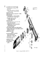
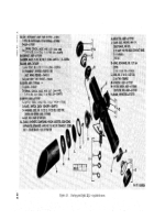
f.Switch .
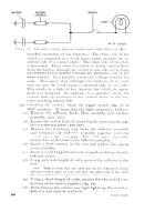
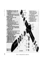
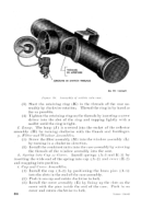
(1) Using a small screwdriver, bend back the two edges of the
lock washer (F-3) that act as a retainer for the switch nut
(F-4) .
that holds the switch (F-1) to the case assembly.
(3) Slip off the lock washer (F-3) and switch plate (F-2).
(4) P
ush the
switch back into the case assembly and remove it
through the reflector opening in the case assembly.
(5) Where required, disconnect the cables (G) leading from the
switch to the contact, by unsoldering the connections at the
switch terminal l
ug S.
Note.
Unsolflcrinx the coumct iou frtnn the writ cl] ternliml Iws
illste:l(l of :It the (’ont~lct, will I’:lcilitiltc soltlerill,q tile ct)llllt,ctit~ll IVhen
:1 new switch is inst :nllwl.
When disconllectill~ the ct~ut:lct (,:lljle
IWI[lS aIIIl the rrflector c:alIle lead at the switch, be sure ttl uote the
si(lc of the switch to JVhich the eont:lcts :tud reiiector nlust be reCou-
]Iectrd.
g. Contact Assembly.
(1) Each contact assembly (B) is held in position in the case
assembly by two flat-head screws (C) which pass from both
sides of the case assembly into the contact assembly. Re-
move the two screws.
(2) Unsolder the cable (G) leading from contact assembly (B)
to switch (F-1) at the switch side. This will facilitate
soldering the connection.
Not(. Where the mmt:lct on tlw C: III side of the ease is being re-
nlt)vc(l for che(,l<ill: I)lwlnws only, it is not IIwt,w}luy to unsol(lel tile
{.allle Collllt,ctioll,” sill(.e the length of the ctlble is elloll:h to lv+lmlit ;I
rt,IIIov:ll ~)t’ the collttlct when the reflector and switch are illsertetl
11:1(11 into the c;lse olwuiu~.
(3) Withdraw the contact by pushing it out of the case with the
finger or by tapping the case lightly against the edge of the
work table.
(4) The contact on the cover side of the case assembly is removed
in the same manner, but it is necessary to unsolder the cable
at the switch in order to permit the removal of the contact.
h. Clamp and Thumb Nut or Wing Nut.
(1) Remove peened end of pins and drive out pins (D-2).
(2) Remove clamp (D-3) and wing nut (D-1).
Note.
On
aiming
post
lights
of early
manufacture, thumb nut
(riveted) was used; lights of present manufacture use wing nut
(peened).
Back to Top

