TM-9-6015 - Page 39 of 54
33
Insert the contact assembly (B) into the end of the case
assembly (D) with the angle strip facing into the case.
Draw the free end of cable lead out through the reflector
opening in case.
Rotate the contact assembly until the threaded holes of the
angle strip are alined with the two threaded holes in the
case assembly.
Secure the contact assembly by installing the two No. 2
of the case assembly into the hole in each side of the angle
strip.
The upper and lower contact assemblies of aiming post lights
(1)
(2)
(3)
(4)
(5 )
(6)
Solder the cables (G) to the correct side of the switch (F-1)
as noted in paragraph
22f.
Reversing the connections will
result in the light being lit when the switch is in the “OFF
”
position a
S indicated by the switch plate.
Insert the switch into the case through the reflector opening
and fit the toggle switch (F-1) through the switch aperture
in the case assembly.
.\’,Jtf ( / ). .N.jlwt the hex nut (F4) on switch so 1 hat switch pro-
t rufl(,s tllr{ ,\IglI :Ilk,rt uw wtfk.iently enon+ih to inst:ill switch plate
(F–2 J , 10(.1< Iv:lsller ( !=1) :111(1 IllIt.
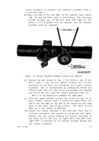
JIOt, ( ? ) Th(, sivit(ll ill]ertllre is providwl with n S1llilll projecting
t~,]lgllt, fig. 18 ), :IIM1 n slot is nm(”hinod iljto the switch screw threads.
I:e sure to nl:~tc the toww and slot when insertiwg the switch into
l){,sitit)n.
With the threaded position of the switch in place in the aper-
ture, slide on the switch plate (F-2). Aline tongue on switch
plate with groove in threads on switch and drop switch plate
in position on switch.
Aline internal lug (tang) on lock washer (F-3) with groove
in threads on switch and instal the washer.
Screw the switch nut on the switch and tighten with a
Bend the lugs of the washer over the flat edge of the nut with
a screwdriver.
.
e. Reflector Assembly.
(1) Make sure that cable lead from the reflector lamp contact to
the switch is securely sosdered at both ends of the lead
(fig. 15).
(2) Insert the reflector assembly (H) into position in the case
assembly.
Back to Top

