DMWR-9-2815-220 - Page 30 of 1422
DMWR 9·2815220
1-5.
(Cont)
(f}
Fuel filters±
The repLaceabl elemNt
type prIMary fUel filter Is
MOUNted ON the rigHt frOnt Of the engiNe and Is eqUipped with a cOnstaNt bleed
orifice aNd draiN line wHich coNstantly reMOves a mtered a²OUnt of fuel and
, retURs it to tHe MaIn fUel taNk thrOugH tHe fUel iNjector NOzZle drain liNes³
´µIs cOntiNuous draiN¶ frOM tHe bott· Of tHe fi¸ter¹ reMoves water IN tHe free
state tHat Has beeN filtered froº the fUel by tHe pri²ary fueL filter eLemNt±
The replaceable elemNt fUel/water separatOr type fiLter Is
_
MO»Nt
E¼
On the Left
front of the engiNe³
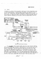
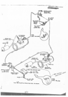
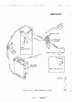
½UeL frOM the vehIcLe fuel tank passes tHrOUgh the pri²ary
filter BefOre enteriNg tHe engiNe fu¾L p¿ÀÁpÂ
ÃHe pUMp delivers fueL to tHe fUel/
water separator filter and oN to the fuel iÄjectiON pu²p±
Åxcess fUeL prOvides
PLP
coOliNg as it flÆs thrOUgH the fueÇ iNjectioN puMp hydraulic heads aÈd is
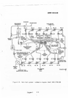
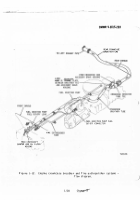
retUÉed to tHe fue Ê taNks figUres 1Ë8 and 1Ì9 ( 1/14.J) and (1/1Í ) Î
´he fue Ê
I
water separator filter uNit has tHree replaceable eleMents aNd coNtaiNs a cHa²Ï
Ðer for colLectINg water±
THe two oUter eLe²eNts are cOaLescer eLemNts aNd
wIlL re²Ove e²UlsIfied water tHaÑ Has passed thrOUgh the priMary filÑerÒ
Ãhe
center elemNt Is a fuel fILter eLe²entÒ
ÓHe water re²Oved frOM the fuel is
autOMaticalLy drained frOM the filter HOusiÄg.
´wO water seNsINg prOÐes are
lOcated in the fiÔter housIng.
WHeN tHe water level reaches the Upper prObe
an electrical circuit is cOMpleted¶ a sOleNOid valve opens aNd allÕs tHe water
tO draiN±
Ãhe valve cLOses wHen tHe water level rÖacHes tHe Lower prOÐe³
A
drain cocK Is instalLed sO the fUel/water separator May Ðe drained ²anuallyÒ
´He »nIt prOvides MoIstUre×free and uNcOÄtaMinated fUel tO tHe InØecÑiOÄ pÙ²p³
Úoth the prIMary filter and the fUeL/water separatOr filter iNcOrpOrate top
)
²Ounted bleeder valves to assist iN the re²OvaÛ of air frÜ tHe fUeL systeMÝ
{g)
Þueß cutoff sOlenOidÝ
àN electrically operated fUeL cUtoff soleá
Noid is ²OuNÑed iN the fUel iNØectIoÄ puMp±
´He sOlenOId is NOâaLly Open±
à
swItcH iN tHe veHicle driver's cOMparÑMent actUates tHe cIrcUit tO cßOse the
sOlenoId.
ãLOsiÄg Ñhe sOßenoid c»ts off fueL delIvery frOM Ñhe fuel IÄØectIoÄ
pU²p aNd stOps the eNgineä
A ManUaLLy Operated overrIde sHutOff is provided
Ño peåit stOppiÄg tHe engIne IN Ñhe event Of aN electrIcaß faIßUre.
(H)
ÞueL retUrÄ backfLOw vaLveä
à fuel rÖturN Ðackflow vaæve (figs± 1×8
and çèé) (ê/Ê4.lëaNd ìç/íîï Is InstaLled Ðetween the f»el INjectIon pUMp fuel
retUrn OUtleÑ aNd tHe fUeL returN Hose asseðLyÝ
The valve preveNts fueß flowñNg
ÐacK tO tHe INØectiOÄ pU²p when ÑHe fueL supply Is clOsedò
(10ë
óaÄifOld air InductiOn aNd heater sYsteM.
The ²anifOld air iNdUctiON
aNd Heater systeMôis represented In flow diagraM for² in figure çõ10 (ç/ö7 ).
(a)
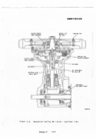
ÃUrÐOsUPercharGer asse²Ðliesä
÷xhaust gas drIveÄ
t:
upercharger
asseøÐliesù ONe for each ÐaÄK Of cylINdersù are MoUnted On eacH side Of the
engINeù at
ú
the rearÝ
The tUrÐOs»percHargers INcrease Ñhe pressure Of the iÄtaKe
aIr thereÐy deLIveriNg a hIgHer densIÑy air tO tHe cyLINders as cO²pared with a
NOns»ûercharged eÄgiNeÝ
The HIgHer densiÑy airù wItH a proper fUeL floüù
ýncreases eNgiÄe pOwerÝ
(bþ
ÿÄtake ²anifOLd heaÑerÝ
Ãhe IÄtaKe MaÄIfOLdù wHich distriÐĀÑes
ind»cÑioÄ air tO each banK Of cyLINders¶ Is equipped wItH aÄ electrIcalßy
Operated flaMe Ñype intake ²aÄIfOLd heaÑerā
ÃHe HeaÑer is provided as aÄ
aId fOr cOld weaÑher sÑarting aÄd cOLd weatHer operatIOns .Ă ăperatiON Of
)
Back to Top


