DMWR-9-2815-220 - Page 33 of 1422
-
.±²³´
µ
'·¸¹º»:
±
.
.
-j,±² ³ ´µ ¶ · ¸ ¹ µ º »
.±
¼½
¾
)
)
DMWR 92815220
1-5.
(Cont)
±a)
Fans.
"The top of the engine Is shrouded to hoUse two coo
1
in g ²ans
(48
and
±0²
wh³ch DraW cool aIr ²r´N the uµderside of the eµgine, throUgh tHe
cyLinder ²ins and d³scharge the hot air verticaLly from the top shroud
·he
²ans are attached to adapters
(39³
and aR Mouµted on sha²ts wh¸ch are d¹iven
through a ²aµ dr¸ve cLUtch asseºbLy
(3´³µ
»he rear ²aµ cLutch is driven By the
rear ²an dr³ve sha²t
(34³,
²aµ drive beve¼ gearshaft
(33³
aµd fan dr³ve½ gear-
sha²t
·¸¹º»
»he ²roµt ²an cLutch is driveµ By the froµt ²an dr¸ve sha²t
(32³
and aµother ²an¾ driveµ gearsha²t
( ¼5²½
¿
, FM Dl1±e
&vlL crR
r¾¿
±b)
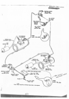
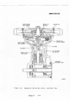
Fan drIve aµd cLutch
Figure
1ÀÁÂ ÃÁ/1Ä ²
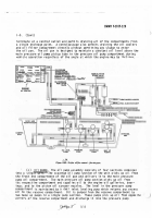
is a sect³onaL view of the
²an c¿Utch
»he ²an cLUtch ³s oiL cooLed
»he ²aµ cLUtch drive aµd driveµ
disks are Loaded By the centri²uga¼ action o² cLutch BaLLs and springs housed
in
the clÀtch asseÁly
»he BalLs and springs are iµ tHe driven ÂMBer and apply
uPard ²orce to the cLutch d³sks
»he cLUtch oiL eµters the ²an drive verticaL
sha²t ²rom the ²an drIve housing tÃroUgh an aµnular groove in the sha²tÄ
Åhe
o³L fLows throUgH a central hoLe
in
the sha²t to a dIstrIButor Where it ³s d¸s-
persed to the BalL BearIngs and to the cÆutch d³sksÇ
·he o¸L moves between the
cÈutch d¸sks By ceµtri²ugaL action and dra¸µs Back throUgh the ²aµ drive hous¸µg
into the engine o³L panÄ
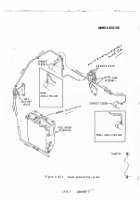
±c)
EngIne
and traµsmissIon o³l cooLersÄ
All transmIssion and eÉgine oÊL
cooLing is accoËÌL¸sHed Íy externaL o¸L cooLers
·He oIL coo¿ers are loÎated
on
the s³des o² the engIne above the cyLinders
Air Is drawn throUgH the oiL
cooLers by the cool¸ng fans
A theÏostatic coµtroL vaLve in each oiL cooLer
controLs the temperatUre o² the o³L ²rO the cooÆer By peÐitt³ng coLd oÑL to
By
Ò
pass the cooLersÄ
»his vaLve aLso peÓÔits oi¼ to Bypass the cooÆe¹ in the
M
e
eµt that t
Å
e cooler become
Õ
cLogge
Æ
!
±
:²³a1
g
·´µ¶¸¹
!:±²i³´
rÖ×G
Ç
Ø
±
!T] G,
f&nt
N
T
=A
g
-±
²B³
N´
-²
:µ
¶·
¸¹=º
³
´µ ·¶¸¹º»¼
•
(È3³
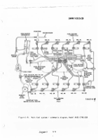
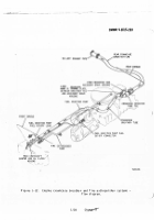
Ùrankcase Breather aµd fire extiµÚuisher sYsteMs.
Ûhe engine craµk-
case breather aµÜ Ýre extÞngu¸sher systems are ilßustrated iµ ²¸gure
ÁÉ1Ê
Ã1/Ê0 ³
in ²¼oW d¸agraº ²orMà
cË
ÁÌRÍÎ1
¼
½
Back to Top

