DMWR-9-2815-220 - Page 23 of 1422
)
)
DMWR 9·2815±220
1-5.
(Cont)
(d±
Valves.
The stem of the intake valve
(±0²
and exhaust vaLve
³49´,
For each cyLInDr,
extends into the Rcker box²
Three nested spr³ngs, coMpressed
between two reta³ne´sµ 
·
and secured to the vaLve stem by two coneshaped
¸
locks¹
hold each valve to ³ts seat.
Each eXhaust valve has a pos³t³ve vaLve rotator
º
wh³ch also serves as the lower spring reta³ner»
Valve cLearance adjustinG
screws w³th flat sw³vel pusher pads a´e ¼unted on one end of the va½ve ´ocker
a N¾s ( L and
2µ
.
.
±
¶e·
¿ocker arÀs²
Áorged steel valve rocker ArÀs
¸¹
and
2º
w³th Âoller
cam-Fol½owers a´e used²
Ãhe ´ol½ers are hardened and honed
t
pÄ
º
ovide an eXtremÅ
e½y sÆoth and peÇnent contact surFace
º
È
HoÉlow rocker aNÊ shafts and driLled
passages ³n the Rcker arms convey o³l to aLL ËÌving parts.
»7¼
ÍamshaFts.
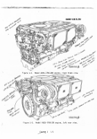
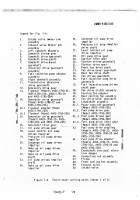
ÎheÏ key nuÀbers ³n parentheses below reFer to figure
1-6 ½1/
8
¾
unless otherwise ³ndicatedÐ
(a)
Ñamshaft asseÀblies.
Îhe leFt and right caÀshaft asseÀbLies
¿3
and
1À}
are ÒuntedÓ one on each bankÔ on the cyÕ³nders and operate the valve ÖchanÅ
ism.
Îhe caÀshaFts are ho½Õow to p´ovide oiL passages For p×Øssure Lubrication
to tÙe valve parts and to perÚ³t defLect³on when the cylinde´s fiÛeº
ÎubUlar
¼lded rubber
encLose the camshafts between cyL³ndersº
:liIYÁ
Üb±
ÍaÝhaFÞ dr³ve.
ßach caàhaft ³s dr³ven by the accessory drive gear
¸1ÂÃÄ
accessory dr³ve gearshaFt asseÀbly
Å8ÆÇ
camshaFt dr³ve bevel gearshaft
ÈÉÊË
camshaFt dr³ve gearshaFt
½5ÃÌ
and camshaft dr³ven gear
Í4Î
tháugh an ³ncl³ned
qu³ÕL type camshaFt dr³ve shaft
½6Ï.
Îhe dr³ve shafts can be ´e¼ved to peâãit
SäåPrate R_tæ
·
Qçèéheê camshaFës FOr eng³ne ti!ìingº
When camshaFts are
correctLy pos³t³oned ³n relation to íÙe cranksîaFtï the drðñe sòafóô have differõ
ent nuÀber of spl³nes on each end and th³s allows them to be ³nserted ³n the
"
ö
÷ams øa Ft beveÕ gùúrû haüts w³ýhout d°þsturbi ng re'l ÿtionshiĀ beātĂăeĄn
¸
ąaĆshaftć
-·
and crankshaft.
(
1/±)
s.±²
cnG,³
Lul1C
²³
/±7²³& sySrT
I>
Å8Æ
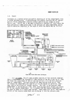
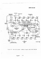
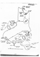
Ĉubrication sYstem. ĉ³gure
1-É
²
²³ s´
Ð
o
L
de l
S
g ´ µ
ybrÑtaTÒEÓsÔÕÖ
ncv¶i
·- ¸A
D
'×
Ø
/´
µ ¶·
J¹
º:» ¼½w ¾.6¿ €ÀÁ,Âã ÄÅÆÇ ÈÉ ÊËÌ
(a}
Ċeneral.
Îhe ċ³n pressure o³l puÀp draws o³l fČm the pressure
o³L pump coÀpartÀent ³n the o³L pan.
Ãh³s compartment is fed by the scavenge
o³l pučp wh³ch pĎcks
ď
up oil frOm the Front end of the oiL pan
Đ
and by o³l wh³ch
drains ³nto the pressure compartđĒnt from the cover of the pressure pump comē
partment and the reserve compartment.
Ãhe pressurized oil is forced through
the eng³ne oiL coolers and oiL Filter to the engine oiL galLer³esÔ bearĔngs,
turbosuperchargersĕ Fuel inJection puÀpÔ and to the p³ston o³l sĖrayer nozzlės²
Ãhese noZĘLes are Located ³n the crankcase below eacÙ cyL³nder and provide a
cont³nuous o³l spray to the pistons and cyl³nder waLls.
a
pressuÛe ´egulator
vaęveï located on the rĎght s³de oF the crankshaFt damper and oĎl f³Õter hous³ngĚ
³s ³nFLuenced by the pressěre in the Ĝĝin bear³ng oiL galLery and returns the
incoming eĞcess unFiLtered o³l to the oiL pan.
(bğ
ĠĎL ġanĢ
The oiL pan is a one-p³ece
aLuĆinuÀ alLoy castģng dĔvided
into a pressure o³L pĤđp coÀpartĥĦntħ oiL reserve coÀpartÀėntĚ and tÙe suÀp
,
.
µ
comĨaÂtđĒnt at the f´ont of the panº
ĩored passages froÀ each of ĪÙe coĆpartīnts
ÙÚ
O
J
'
'
´
'
µ
)
'
S
¶1(
Û /¹¹
Back to Top

