DMWR-9-2815-220 - Page 22 of 1422
DMR 9·2815-220
\
)
1-5.
(Cont)
±b)
BeariNg ourNals.
tl
1R
s
La J
.r ±Tc
:BigM
.
Holes are drilleD dIaGonally thROuGh each m²N bea³inG
joUrnal and exteNd th´UGh the crank cheek aNd crankp²n
µ
t¶ p·vide a Direct
passaGe for oil UNDer press¸re to the conNectING ´D and craNkshaft m¹N beariNGsº
_
(±4)
»oNnect¼n½
´ds and beariN¾s.
The coNn
e
ctinG
_
roD asse¿ÀLiÁs
{²6,
FiG
'
Â
h§L ³l´8
µ
ÃÄÅ-ÆpereÇ
_
È
:Ée!M
Ê
sec
t
Of
_
sËee
²
foÌG¹ nGsÍÎÏ Ð
Ñ
PronÒÓ
ÔÑ
l
±
nED, steeÕÖ
backeD× spØÙt b¸shinG Úpe beariNG Is presseD Into the piston pIn enD of tÛe ÜodÝ
Þhe replaceable precisioN connectiNG RoD bearInGs ßre the steelàbackeDá split
type havinG copperâleaD alØoy bearinG sUrfaces.
¶5·
ãistonsä åinsæ anD rIn½sç
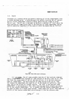
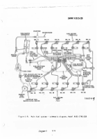
The pistoNs
¸¹7º
fiGç
»-¼½ ¾¿/ ÀÁ
arè
aØUMinUM castéNGs, caê G´¸NÇ,
Ê
aN
ë tapereD to proviDe aN accurate fIt 1n tÛe
cyLinders at operatiNG teMperat¸resç
Þhe piston ìí is îchiNeD to the shape
of a conical sectioN ïð¶ridaL shape) so that it tapers iNto the opeN type
coñUstIon chaMberò
óach pistoN is fitted with FoUr rinGsç
ôhe top rinG Gr¶ove
is coõoseD of a steeL INsert Which is an ¹ntreGal part öF the pistoN.
The three
rem÷ninG rinG Gøoves are ùchiNeD into the al¸êinuM pistoNç
The Upper three
rinGs are coMpressioN rinGs and the bottoê riNG is an oIlâcontroL rinG.
The
heavy WaLLeD× tubUlar× steel pistoN púNs are FUllûfloatinG IN the pistoN AnD the
conNectiNG RoDü
ÞÛe pist¶N pIn
ý
Is retaiNeD Jþ{the pistoN by retaiNinG rinGs×
oNe at each end oF the pIstoN pIn× IN the pistoN pÿN bore.
¼½
C LINders and valvesç
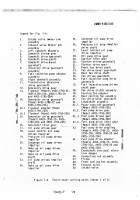
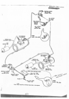
The Key nuĀāers in pareNtheses beloW rĂfer to
)
fiGure
ÃÄ6 Å/ À
unLess otheăise inDicatedç
Ąa)
»YliNDer asseąLĆ.
ćach cylInder asseMbly is aN INdivIDually reĈ
pLaceable ¸Nĉt tÛat coNsIsts of a barrel× cooliNG fiN M¸FfĊ anD a cyØinder ÛeaD.
The cyLinder barreL× doċ aNd iNtake aND exhaUst port lČners are steel.
Þhe
aL¸čiN¸č cylinder heaD cooLInG Fins arĎ cast to the steel Doí.
ďhe coolinG
fiNs for the barrel are ùchiNed iNto aN aظMiN¸ê MĐff anD shrUNk onto the steel
barreØç
đfter tÛè cyLINDer barrel fins are Ēchined, the hEad aNd barrel are
electR¶N beaM WeLded to forM a siNGle ¸Nit.
Valve GUides anD seats are shrUNk
Into place IN the head.
The cylinder barrel is "choKeDē at the heaD enD to
provIDe a straIGht bore ĐNder rUNNĔnG conDitionsº
ĕb)
ĖYLúNDer asseMbLė ĘUNtINę.
đ ̸ntinG ělanGe is ùchineD on the
cylinDer barrel near the base to pĜOviDe
ĝ
aĞ attachğnt of the cyliNDer to the
crankcaseç
The cylĠnDer asseMbġy is secureD to the crankcase w²th stuDs anD
nutsç
đn outer exteNsioN of the cylInDer heaD encloses a recess or rocker box×
whIch houses the valvesä vaØve sprinGs× anD relateD parts.
Ģocker arM asseêĈ
bØies
ÆÃ
anD
2Ç
are helD iN pØace by ´cker sÛafts in the cylInDer heaD valve
rOcker sUpport cover.
±cģ ĖaĤShaFt bearINĥç
đ caMshaFt beariNG sUrFace is pĜovideD In each
cyØinderç
Þhe caMshaFt beariNG Is boreD wIth
Ħ
the cyLinder head vaLve RocKer
support cover IN pØace; thereForeħ the covers are Not inteÜchaNGeable aNd each
MUst reĒIN as a part of a specIfIc cyLiNDer asseĨlyç
ćach cyliNDer has reĈ
placeable caMsÛaft beariNGs at the caMshaFt boreç
ĩdeNtiFyinG NUMbers are ¸sed
oN cyLiNder aND covers to preveNt êisĪtchINGò
Ėo¸Nterbores IN the rocKer box
_
aNd ܶcKer sīpport covers accoĬĭĮįDate the INtercyLInder rUbber İand the
steeL FLaNGes ıhIch eNclose tÛe caMsÛaFt betWeeN the cyLINdersü
²/²³
Back to Top

