MWO-9-2320-272-35-1 - Page 14 of 109
MWO 9-2320-272-35-1
12
(12)
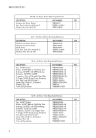
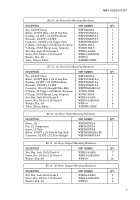
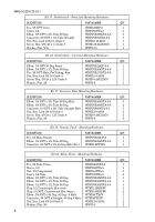
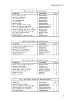
Apply a thin coat of Molykote CU7439 or equivalent to bore of WHMB200817Z sensor mounting
bracket as shown in figure 3. Align tabs and push WHMB59512309 sensor clip into rear of
sensor mounting bracket (WHMB200817Z).
(13)
Apply a thin coat of Molykote CU7439 or equivalent to sensor barrel and push sensor barrel into
sensor clip (WHMB59512309) until shoulder of WHMB364208011 sensor contacts sensor clip
tabs as shown in figure 3.
(14)
Remove existing three nuts, screws, and six washers from brake spider plate as shown in figure 3.
(15)
Position sensor cable in slot on sensor mounting bracket (WHMB200817Z) and route sensor
cable along forward side of axle flange, flush against spider plate as shown in figure 3.
CAUTION
CAUTION
Make sure sensor cable is in slot before tightening screw.
(16)
Install sensor mounting bracket (WHMB200817Z) on brake spider plate with two WWF9-16
washers, WSH9-16-18X225G8 screws, WWF9-16 washers, and WNHL9-16-18G8 locknuts as
shown in figure 3. Tighten screws 110-145 lb-ft.
(17)
Secure sensor cable to brake spider with WCND5-16X9-16 clamp, existing washer, screw,
washer, and nut. Hold screw and clamp and tighten nut 110 lb-ft.
CAUTION
CAUTION
Verify that sensor cable doesn’t contact moving brake components
after installation.
(18)
Route sensor cable through 0.625-in. hole in brake adjusting slot and install WHRC10105
grommet on sensor cable. Pull sensor cable tight and install grommet (WHRC10105) and sensor
cable in brake adjusting slot as shown in figure 3.
CAUTION
CAUTION
Cap or plug all hoses, tubes, lines, connections, and openings
immediately after disconnection to prevent contamination.
Remove caps or plugs prior to installation. Failure to do so may
result in damage to equipment.
NOTE
NOTE
• Refer to table 3 for torque on tubing nuts.
• Perform steps 19 through 20 for M939A2 vehicles.
(19)
Loosen tube nut and two CTIS bracket screws and move CTIS tube back away from elbow as
shown in figure 4.
NOTE
NOTE
Note position of elbow for installation.
(20)
Loosen jamnut and remove existing elbow from CTIS flange as shown in figure 4.
(21)
Install WTFD8C50X-S elbow on CTIS flange and connect tube to elbow as shown in figure 4.
Tighten jamnut, tube nut, and two CTIS bracket screws. Tighten screws 110-140 lb-ft.
(22)
Route sensor cable along side of brake chamber and secure with WTS800UVBK tiedown straps
every six inches as shown in figure 5.
(23)
Install rear-rear axle brakeshoes. (Refer to TM 9-2320-272-24.)
NOTE
NOTE
Do not install axle shafts until after final check valves test is
performed (para. 10.h).
(24)
Install rear-rear axle drum and hub. (Refer to TM 9-2320-272-24.)
NOTE
NOTE
Perform step 25 for M939A1/A2 vehicles only. Perform step 26 for
M939 vehicles.
(25)
Install rear-rear wheels and tires. (Refer to TM 9-2320-272-24.)
Back to Top

