MWO-9-2320-272-35-1 - Page 15 of 109
MWO 9-2320-272-35-1
13
(26)
Install all wheels and tires including spare. (Refer to TM 9-2320-272-24.)
NOTE
NOTE
Doublecheck valve No. 2 is used for all vehicles except
M931/M932 vehicles. Doublecheck valve No. 5 is used for
M931/M932 vehicles.
(27)
Remove doublecheck valve No. 2 (figure 6) or doublecheck valve No. 5 (figure 7) from frame rail.
(Refer to TM 9-2320-272-24.)
Do not disconnect air lines at this time.
(28)
Remove two red tubes, elbow, and tee from doublecheck valve No. 2 as shown in figure 6, or
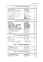
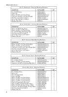
doublecheck valve No. 5 (M931/M932) as shown in figure 7, and install WBPDVS269NTA-6-6
elbow as shown in figures 7 and 8.
NOTE
NOTE
M928 models use existing screw for mounting valve.
(29)
Install doublecheck valve No. 2 or doublecheck valve No. 5 (M931/M932) on frame rail with
WSH5-16-24X100G5 screw, WWF5-16 washer, and WNHL5-16-24G-5 nut as shown in
figure 7 or 8.
(30)
Remove eight existing screws, washers, and cover from driver’s side step box as shown in
figure 9.
NOTE
NOTE
Remove existing tiedown straps on air lines as necessary.
(31)
Remove existing nut, screw, and clamp with air lines from step brace as shown in figure 9.
(32)
Measure 1.50-in. in from outside edge and mark a line as shown in figure 10. Measure 6.00-in.
up from bottom edge and mark a line across 1.50-in line. Drill 25/64-in. diameter hole in rear
side wall of step box at line crossing.
(33)
Temporarily mount WHMBN50002B inversion valve level on outside of step box with screw.
Using valve mounting bracket as a template, drill 25/64-in. diameter hole through step box as
shown in figure 10. Remove screw and inversion valve (WHMBN50002B) from step box.
CAUTION
CAUTION
Cap or plug all hoses, tubes, lines, connections, and
openings immediately after disconnection to prevent
contamination. Remove caps or plugs prior to installation.
Failure to do so may result in damage to equipment.
(34)
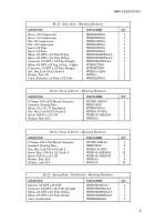
Install WBPDVS68NTA-6-4 connector in BAL port on inversion valve (WHMBN50002B) and
three WBPDVS269NTA-6-4 elbows in control port, supply port, and delivery port, position
elbows facing out the same as adapter as shown in figure 11.
(35)
Disconnect existing tube from bottom elbow on doublecheck valve No. 4 and side elbow on
doublecheck valve No. 3. Remove existing elbows from doublecheck valves No. 3 and No. 4 as
shown in figure 12.
(36)
Install inversion valve (WHMBN50002B) on inside of driver’s step box with two WWF3-8 washers,
WSH3-8-24X125G8 screws, WWF3-8 washers, and WNHL3-8-24G8 locknuts as shown in figure 13.
NOTE
NOTE
Cut tubing length as required.
(37)
Install WBPDVS269NTA-6-6 elbow on bottom of existing doublecheck valve No. 4 and connect
WPFT-6B-500 tube to elbow with sleeve and nut. Route tube (WPFT-6B-500) over to supply port
elbow on inversion valve (WHMN50002B) and connect with sleeve and nut as shown in figure 14.
(38)
Install WBPDVS269NTA-6-6 elbow on side of existing doublecheck valve No. 3 and connect tube
(WPFT-6B-500) to elbow with sleeve and nut. Route tube (WPFT-6B-500) over to delivery port
elbow on inversion valve (WHMBN50002B) and connect with sleeve and nut as shown in
figure 14.
Back to Top

