MWO-9-2320-272-35-1 - Page 23 of 109
MWO 9-2320-272-35-1
21
(147)
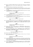
Route harness sensor cables labeled 2A blue and 2B yellow through crossmembers to rear-rear
axle manifold as shown in figure 58.
(148)
Route cable with yellow tag labeled valve through crossmembers to rear relay valve and connect
to valve as shown in figure 58.
(149)
Route two wheel speed sensor cables from rear-rear axle along brake hoses to rear-rear axle
manifold. Attach sensor cables to brake hoses with WTS800UVBK tiedown straps every 6-in.
Connect driver side wheel speed sensor cable to harness sensor cable labeled 2A. Connect
passenger side wheel speed sensor cable to harness sensor cable labeled 2B. Install
WHMB100469F sensor connector latch at each sensor connection point and secure sensor cables
to nearest brake hose as shown in figure 59.
(150)
Connect cable with blue tag labeled valve to forward relay valve as shown in figure 58.
(151)
Route harness power cable and diagnostic cable forward along passenger side frame rail
(figure 58) through crossmembers, avoiding sharp edges or moving parts. Secure cables with
WTS800UVBK tiedown straps every 6-in. Once near primary manifold, follow primary foot
valve hose to foot valve. Feed cables up along firewall and pass diagnostic cable first and then
power cable through hole in firewall as shown in figure 60.
(152)
Remove cap from existing auxiliary power lead No. 10 on firewall. Attach WEL10464 fusible
straight harness (15 amp) connector to power lead No. 10 and route other end and fuse holder
through hole in firewall as shown in figure 60.
(153)
Remove lower mounting bolt and washer from control box on firewall. Place ring terminal from
WEL20516-B ground Y-harness onto bolt and install washer and bolt into control box on
firewall. Route other end of ground Y-harness through hole in firewall as shown in figure 60.
(154)
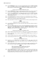
Place WHRCAN931-A12-23 grommet around cables and insert grommet into hole in firewall as
shown in figure 61.
(155)
Install WHMB102008SP diagnostic connector mounting bracket on brace under dash on
passenger side next to STE/ICE-R connector in existing hole with WSPP10-32X75 screw and
WNKL10-32 locknut as shown in figure 61.
(156)
Using mounting bracket as a template, mark and drill 21/64-in. diameter hole in brace as shown
in figure 61.
(157)
Secure mounting bracket to brace with WSH5-16-24X100G5 screw and WNH5-16-24G5 locknut
in hole drilled in step 156 as shown in figure 61.
(158)
Route diagnostic cable connector under dash over to passenger side and secure with
WTS800UVBK tiedown straps as shown in figure 61.
(159)
Remove diagnostic connector cap, mounting nut, and cap retainer from connector and install
connector on diagnostic bracket with cap retainer and mounting nut. Install cap on connector as
shown in figure 61.
(160)
Locate, mark, and drill a 13/32-in. diameter hole in gauge panel as shown in figure 62. Using
WMS1007 ABS warning label as a template, drill two 9/64-in. diameter holes in gauge panel as
shown in figures 62 and 63.
(161)
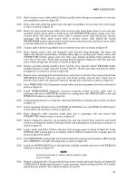
Insert WEL202023 warning light into hole from back side of gauge panel and place ABS warning
label (WMS1007) over light and align holes as shown in figure 63.
(162)
Install two WSPP6-32X075 screws through label and light assembly and secure with WNKL6-32
locknuts as shown in figure 63.
NOTE
NOTE
It may be necessary to remove starter switch to gain
access to lead.
(163)
Remove existing lead No. 54 at position R from starter switch and install female end (labeled R)
of WEL20516-A fusible pigtail harness (3 amp) connector. Attach existing lead No. 54 to fusible
pigtail harness lead No. 54 as shown in figures 64 and 65.
Back to Top

