MWO-9-2320-272-35-1 - Page 20 of 109
MWO 9-2320-272-35-1
18
(106)
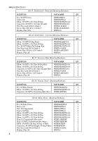
Install WPFT-8B-500 tube on elbow (WBPDVS269NTA-8-6) at forward-rear axle manifold block
with sleeve and nut as shown in figure 42. Install other end of tube on driver’s side service brake
chamber with WBPD63NTA-8 insert, WBPD60NTA-8 sleeve, and WBPD61NTA-8 nut as shown
in figures 41 and 43.
(107)
Install WPFT-8B-500 tube on existing adapter at forward-rear axle manifold block (driver’s side)
with WBPD63NTA-8 insert, WBPD60NTA-8 sleeve, and WBPD61NTA-8 nut as shown in
figure 42. Install other end of tube (WPFT-8B-500) on elbow at passenger side spring brake
chamber with WBPD63NTA-8 insert, WBPD60NTA-8 sleeve, and WBPD61NTA-8 nut as shown
in figures 41 and 43.
NOTE
NOTE
Perform steps 108 through 112 for rear-rear axle.
(108)
Remove existing 1/2-in. green tube from rear-rear axle manifold block and driver’s side service
brake chamber as shown in figure 44.
(109)
Remove existing 1/2-in. orange tube from rear-rear axle manifold block and passenger side
spring brake chamber as shown in figure 44.
NOTE
NOTE
It may be necessary to remove insert from elbow for
installation.
(110)
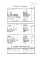
Remove existing adapter from rear-rear axle manifold block (passenger side) as shown in
figure 44, and install WBPDVS269NTA-8-6 elbow facing rear on manifold block as shown in
figure 42.
(111)
Install WPFT-8B-500 tube on elbow (WBPDVS269NTA-8-6) at rear-rear axle manifold block
with sleeve and nut as shown in figure 42. Install other end of tube on driver’s service brake
chamber with WBPD63NTA-8 insert, WBPD60NTA-8 sleeve, and WBPD61NTA-8 nut as shown
in figures 41 and 45.
(112)
Install WPFT-8B-500 tube on existing adapter at rear-rear axle manifold block (driver’s side)
with WPBD63NTA-8 insert, WBPD60NTA-8 sleeve, and WBPD61NTA-8 nut as shown in
figure 42. Install other end of tube (WPFT-8B-500) on elbow at passenger side spring brake
chamber with WBPD63NTA-8 insert, WBPD60NTA-8 sleeve, and WBPD61NTA-8 nut as shown
in figures 41 and 45.
NOTE
NOTE
Perform steps 113 through 118 for M939/A1 only.
(113)
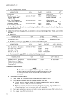
Remove alcohol evaporator reservoir. (Refer to TM 9-2320-272-24.)
(114)
Remove steel tubing between alcohol evaporator reservoir and air compressor intake manifold
as shown in figure 46.
(115)
Remove elbow from air compressor intake manifold and install WTFD1-8HHPSV plug in open
port of air compressor intake manifold as shown in figure 46.
NOTE
NOTE
Pipe plug may be located on top or front of governor.
(116)
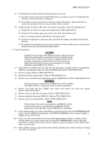
Remove hex pipe plug from unloader port between two mounting bolts on front side of governor
mounted on firewall as shown in figure 47.
(117)
Install WBPDVS216P-2 nipple in governor unloader port and WBPD2200P-2-2 elbow facing
driver side on nipple. Install WBPDVS48F-4-2 connector on elbow (WBPD2200P-2-2) and
connect
WHRHTH-1-4-96 hose to connector as shown in figure 47.
(118)
Route and secure hose (WHRHTH-1-4-96) with WTS800UVBK tiedown straps every 6-in. across
firewall toward driver side until it reaches existing hoses from foot valve, route down to driver’s
side frame rail above transmission mount towards rear of vehicle.
Back to Top

