MWO-9-2330-390-25-1 - Page 7 of 54
MWO 9-2330-390-25-1
5
10.
MODIFICATION PROCEDURE.
WARNING
Use extreme caution when handling heavy parts.
Lifting device is required
when parts weigh over 50 lb (23 kg) for a single person lift, over 100 lb (45
Kg) for a two person lift, and over 150 lbs (68 kg) for a three or more person
lift.
Keep clear of heavy parts supported only by lifting device.
Failure to
follow this warning may cause serious injury or death to personnel
NOTE
•
Hydraulic lines should be tagged before removal.
•
Positioning cylinder ports should be plugged with masking tape or other
suitable means as lines are disconnected or fittings are removed.
•
A suitable container should be used to catch any draining hydraulic fluid.
Ensure that all spills are properly cleaned.
a.
DOLLY PREPARATION
NOTE
•
Preparation procedures are the same for front and rear dollies.
1.
Uncouple Dolly set from Tow vehicle
2.
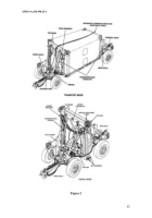
From the transport or travel mode (Figure 2) perform operations needed to
detach front and rear dollies (Refer to Appendix A).
3.
Place front and rear dollies into maneuvering position (Figure 3) and separate
by a distance of at least 30 ft or side by side. (Refer to Appendix B, Section a).
4.
Place wooden blocks (12”x12” stock) under each end of each bottom beam
and remove dolly half from maneuvering position (Refer to Appendix B,
Section b).
Once the set is resting on blocks, place wheel chocks under each
wheel.
The condition of each dolly half should resemble Figure 4.
5.
Remove from top and bottom beams all detent lanyard pins, top hooks,
hanger brackets (front dolly), and toolbox (front dolly).
Set aside for
installation to modified structure.
6.
Remove the top and bottom beams and positioning cylinders from both the
front and rear dollies (Figure 5) (Refer to Appendix C, Section a).
7.
Clean and inspect all parts (Refer to Appendix C, Section b).
b.
INSTALLATION
NOTE
•
Installation procedures are the same for the front and rear dollies.
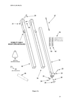
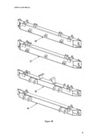
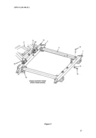
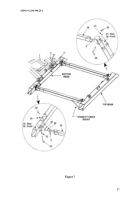
Figure
6 & 7 illustrates installation for the front dolly.
Back to Top

