MWO-9-2330-390-25-1 - Page 8 of 54
MWO 9-2330-390-25-1
6
•
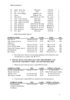
Mounting hardware must face outward to prevent interference.
1.
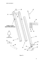
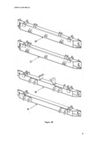
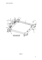
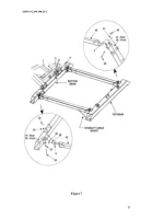
Attach the top and bottom beams and positioning cylinders to both the front
and rear dollies (Figures 6 & 7) (Refer to Appendix C, Section b).
2.
Install both stability cables (27) to mounts provided as shown in Figure 6
3.
Install instruction plates on front dolly upper vertical tube (note the provided
pre-drilled holes). Position first plate (uncoupling instructions) 25” below
upper beam on front upper left (hydraulic valve side) vertical tube. Position
second plate (coupling instructions) ½” below the first plate. Use #4-3/16
drive screws (32) to attach.
A second set of instruction plates is provided with
the kit to be similarly attached to the rear dolly half.
Replace original
shipping data plate on vehicle tow bar with new plate (94) using #4-3/16 drive
screws (32)
4.
Install hanger brackets (front dolly). Position previously removed hanger
bracket on upper vertical tube (34), 8 in (15.2cm) below top beam (19 – Rear,
20 Front). Reinstall U-bolt, and two flat washers with new locknuts.
5.
Install all detent lanyards pins, top hooks and toolbox previously removed.
NOTE
•
Prior to operation of the modified Dolly set, properly check hydraulic
system for leaks and bleed if needed (Refer to Appendix D).
6.
Remove wooden blocks (12”x12” stock) under each end of each bottom
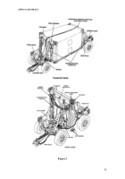
beam and place dolly half into maneuvering position (Figure 3) (Refer to
Appendix B, Section a).
7.
Perform operations needed to return dollies to travel or transport mode.
11.
CALIBRATION REQUIREMANTS.
Not applicable to this MWO
12.
WEIGHT AND BALANCE DATA.
a.
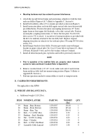
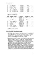
Additional weight (1118.2 lbs).
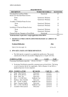
ITEM NOMENCLATURE
PART NO.
WEIGHT
(lbs)
QTY.
19
Beam – Rear, Bottom
12501507
158.50
1
20
Beam – Front, Bottom
12501504
165.44
1
21
Beam – Rear, Top
12501508
206.41
1
22
Bolt – 7 x ½ UNC, Hex
12501533
0.52
4
23
Bushing – Steel, Shoulder
12501523
0.25
8
24
Nut – ½ UNC, Locking
12501532
0.03
4
25
Shim – Cylinder
12501516
1.24
4
26
Bolt – ¼ UNC, Flat Head
12501538
0.02
12
27
Assembly-Cable Lanyard
12501535
1.40
4
Back to Top

