SMI-9-2320-387-14P-1 - Page 392 of 671
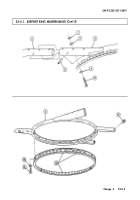
25-4.1. SUPPORT RING MAINTENANCE
This task covers:
a. Removal
c. Assembly
b. Disassembly
d. Installation
INITIAL SETUP:
Applicable Models
M1151
Tools
General mechanic's tool kit:
automotive (Appendix B, Item 1)
Materials/Parts
Six spring pins (Appendix G, Item 246.1)
Eight locknuts (Appendix G, Items 106)
Eight locknuts (Appendix G, Item 108)
Assembled locknut (Appendix G, Item 194)
Personnel Required
One mechanic
One assistant
Manual References
TM 9-2320-387-24P
Equipment Condition
• Turret bearing removed
(para. 11-55.4).
• Roof removed (para. 25-3.1).
Maintenance Level
Direct support
NOTE
Note location of attaching hardware for installation.
1.
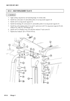
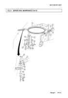
Remove two locknuts (6), washers (3), capscrews (4), washers (3), and front supports (2) from front
mounting clevises (5). Discard locknuts (6).
2.
Remove four locknuts (14), capscrews (9), two striker plates (8), and strap brackets (15) from
B-pillars (12). Discard locknuts (14).
3.
Remove four locknuts (13), washers (11), capscrews (10), washers (11), and support ring (1) from two
B-pillars (12). Discard locknuts (13).
4.
Remove four edge trim strips (7) from B-pillar covers (16).
5.
Remove capscrew (24), washer (23), snubber (19), mount (20), bushing (22), mount (20),
snubber (19), shim(s) (18) if present, and plate (17) from support ring (1) and C-pillar support
bracket (21).
6.
Remove support ring (1) from vehicle.
a. Removal
SMI 9-2320-387-14&P-1
25-6.2
Change 4
Back to Top

