TB-9-2320-280-35-13 - Page 80 of 148
5-52
TB 9-2320-280-35-13
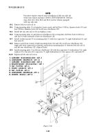
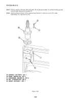
5. CAPSCREW – B1821BH025C125N – QTY. 4
6. LOCKWASHER – MS45904-72 – QTY. 16
7. CAPSCREW – B1821BH031C100N – QTY. 8
8. RESILIENT MOUNT – MT-6146/VSQ-1 – QTY. 1
9. NUT – 9417954 – QTY. 8
11. SPACER – A3046313 – QTY. 4
13. NUT – 9419143 – QTY. 4
14. LOCKWASHER – MS45904-68 – QTY. 4
15. WASHER – 2436161 – QTY. 8
Figure 5-69.
~
12
9
6
13
14
15
16
15
5
4
6
7
8
1
6
9
6
7
10
4.25
NOTE
Procedure requires removal and reinstallation of left rear side rail,
which may require assistance. (Refer to TM 9-2320-280-20.) Perform
steps 18-3, 18-5, 18-6, 18-8, and 18-10 only for vehicles equipped
with rear side rails.
18-3.
Remove left rear side rail (4).
18-4.
Using mounting plate (1) as template, locate, mark, and drill four 0.343-in. diameter holes (10) and
four 0.281-in. diameter holes (16) in left rear wheelhouse (12).
18-5.
Install left rear side rail (4). Do not tighten screws.
18-6.
Using mounting plate (1) and left rear wheelhouse (12) as templates, drill four holes in left rear
side rail (4) from underside of left rear wheelhouse (12).
18-7.
Install resilient mount (8) on mounting plate (1) with four capscrews (7), eight lockwashers (6), and
four nuts (9).
18-8.
Remove paint from vicinity of eight mounting holes (16) and (10) on left rear wheelhouse (12).
Apply anti-seize compound as required, and position mounting plate (1) between left side rail (4)
and left rear wheelhouse (12). Align all holes.
18-9.
Install mounting plate (1) on left rear wheelhouse (12) with four capscrews (5), lockwashers (14), eight
washers (15), four nuts (13), capscrews (7), eight lockwashers (6), four spacers (11), and nuts (9).
18-10.
Tighten all left side rail screws.
11
Back to Top


