TB-9-2320-280-35-14 - Page 38 of 148
5-16
TB 9-2320-280-35-14
9-3.
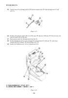
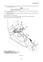
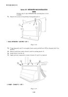
Attach control cable (5) to MT-6353/VRC mounting base (1).
9-4.
Attach power cable (6) to MT-6353/VRC mounting base (1).
9-5.
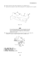
Route control cable (5) and power cable (6) through hole in back of integrated rack.
9-6.
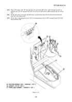
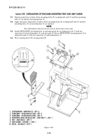
Attach MT-6353/VRC mounting base (1) to integrated rack (3) with two capscrews (9) and (10), six
lockwashers (8), and nut strip (7).
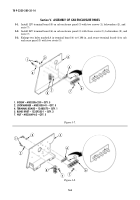
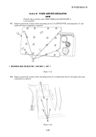
Figure 5-23.
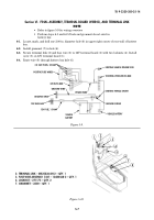
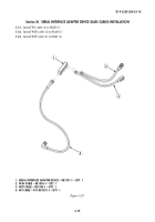
Figure 5-24.
3
7
1
10
8
8
9
7. NUT STRIP – A3014064-1 – QTY. 1
8. LOCKWASHER – MS45904-72 – QTY. 6
9. CAPSCREW – B1821BH031F125N – QTY. 2
10. CAPSCREW – B1821BH031F075N – QTY. 2
5
1
6
5. CONTROL CABLE – A3014037-4 – QTY. 1
6. POWER CABLE – A3014040-9 – QTY. 1
5
6
Back to Top

