TB-9-2320-302-13-P-1 - Page 150 of 380
TB 9-2320-302-13&P-1
ESCAPE HATCH REPLACEMENT - CONTINUED
0027 00
0027 00-2
REMOVAL
1.
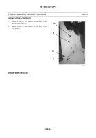
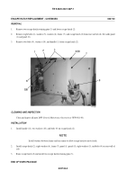
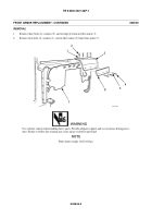
Remove two escape hatch retaining pins (3) and lower escape hatch (2).
2.
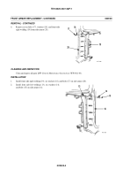
Remove eight bolts (4), washers (5), washers (6), frame (7), and escape hatch (2) from rear wall of cab. Set aside panel
(1) and panel (8).
3.
Remove two bolts (9), washers (10), and handle (11) from escape hatch (2).
CLEANING AND INSPECTION
Clean and inspect all parts IAW
General Maintenance Instructions
(WP 0011 00).
INSTALLATION
1.
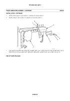
Install handle (11), two washers (10), and bolts (9) on escape hatch (2).
NOTE
Install washers between frame and rear armor to allow escape hatch to move freely.
2.
Install escape hatch (2), eight washers (6), frame (7), panel (1), panel (8), eight washers (5), and bolts (4) on rear wall of
cab.
3.
Raise escape hatch (2) and install two escape hatch retaining pins (3).
END OF WORK PACKAGE
Back to Top

