TB-9-2320-335-13-P - Page 304 of 680
15-4. LEFT CYLINDER HEAD REPAIR
This task covers:
a. Removal
c. Installation
b. Repair
INITIAL SETUP:
Tools
General mechanic’s tool kit:
automotive (Appendix B, Item 1)
Maintenance and repair shop equipment:
automotive (Appendix B, Item 2)
Materials/Parts
Gasket (Appendix A, Item 53)
Antiseize compound (Appendix C, Item 16)
Pipe sealing compound (Appendix C, Item 62)
Cylinder head lifting device
(Appendix D, Fig D-111) (Optional)
Personnel Required
One mechanic
One assistant
Manual References
TM 9-2320-387-24-1
TM 9-2320-387-24P
TM 9-2815-237-34
Equipment Condition
•Fuel drain-back tube removed
(TM 9-2320-387-24-1)
•Alternator/power steering mounting bracket
removed (TM 9-2320-387-24-1)
Equipment Condition (Contd)
• Left exhaust manifold removed
(TM 9-2320-387-24-1).
• Left intake manifold removed
(TM 9-2320-387-24-2).
• Water crossover removed (para. 3-79.1).
• Rocker arm shafts and pushrods removed
(TM 9-2320-387-24-2).
• Fuel injection return hoses removed
(TM 9-2320-387-24-1).
• Fuel injection nozzles removed
(TM 9-2320-387-24-2).
• Glow plugs removed (TM 9-2320-387-24-1).
• Oil pressure sending unit removed
(TM 9-2320-387-24-1).
General Safety Instructions
Cylinder head must be supported during
removal and installation.
Maintenance Level
Direct support
TB 9-2320-335-13&P
15-8
WARNING
Cylinder head must be supported during removal and installation. Failure to
support cylinder head may cause injury to personnel or damage to equipment.
1.
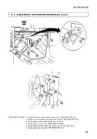
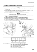
Disconnect harness lead 33B (5) from engine temperature sending unit (4).
CAUTION
Cover or plug all hoses, connections, and openings immediately after
disconnection to prevent contamination. Remove all covers or plugs prior to
connection.
2.
Remove seventeen capscrews (2) from cylinder head (1) and cylinder block (6). Discard capscrews (2).
NOTE
Use of cylinder head lifting device is optional.
2.1. Install cylinder head lifting device (2.1) on center of cylinder head (1) with two washers (2.3) and
capscrews (2.2).
3.
Remove cylinder head (1) and gasket (3) from cylinder block (6). Discard gasket (3).
3.1. Remove two capscrews (2.2), washers (2.3), and cylinder head lifting device (2.1) from cylinder
head (1), if installed.
4.
For cylinder head (1) and valve repair procedures, notify general support (TM 9-2815-237-34).
1.
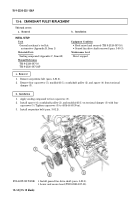
Extract broken portion of bolt (8) from cylinder head (1).
b. Repair
a. Removal
Back to Top


