TB-9-2350-368-25 - Page 10 of 120
TB 9-2350-368-25
ii
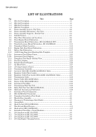
LIST OF ILLUSTRATIONS
Fig
Title
Page
1-1
1-2
1-3
1-4
2-1
2-2
2-3
2-4
2-5
2-6
2-7
2-8
2-9
2-10
2-11
2-12
2-13a
2-13b
2-14
2-15
2-16
2-17
2-18
2-19
2-20
2-21
2-22
2-23
2-24
2-25
2-26
2-27
2-28
2-29
3-1
4-1
4-2
4-3
4-4
4-5
4-6
4-7
4-8
5-1
A-1
A-2
A-3
A-4
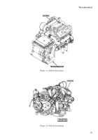
M113A3 Powerplant………………………………………………….…………….
....
M113A2 Powerplant…….…………………………………………………….………
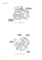
M548A3 Powerplant……………………………………………………………………
M548A1 Powerplant………………………………………………………………….
.
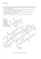
Frame Assembly Layout—Top View.……………………………………….
..…….
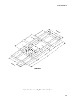
Frame Assembly Dimensions—Top View.…………………………….
..…………
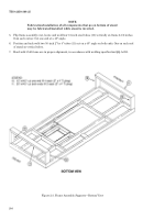
Frame Assembly Supports—Bottom View.
..…….
.…………………….
..…….….
Forklift Pockets…………………………………………………………………………
Floor Plate Dimensions and Locations……….………………………………….
...
Front-Engine Mount Fabrication.
..……………….
.……………………………….
.
Transmission Mount Fabrication—M113A3/M548A3 FOV….………………….
Transfer-Gearcase Mount Fabrication—M113A2/M548A1…………………….
.
Powerplant Mount Location……………………………………………………….
...
Engine-Only-Rear Mount Fabrication.
.………………………………………….…
Battery Box Fabrication………………………………………………………………
100/200-Amp Regulator Mounting Hole Template.
.………………………………
Instrument Panel Hinge Points…………………………………………………….
.
Instrument Panel Support……………………………………………………………
Powerplant Test Stand—Bottom View…………………………………………….
Fuel Line Adapter.
...……………………………………………………….
.…………
Radiator Bracket/Support………………………………………………………….
...
Air Bleed Valve……………………………………………………………………….
..
100-Amp Connector Panel………………….….………………………………….
....
Transmission Controller………………….………….……………………………….
Accessory Cable (M113A2/M113A3/M548A1 Only)………………………………
Regulator Cable (Three Leads)………………………………………………………
Regulator Cable (Four Leads) (M113A2/M113A3/M548A1 Only)………………
Transmission Cable……………………….
..…………………………………………
Starter Cable (M113A3/M548A3)……………………….
..…………………………
Starter Cable (M113A2/M548A1)……………………………………………………
Instrument Panel/Box…………………….……………………………………………
Transmission Stall Test Tool…………….
..…………………………………………
Brake Stall Test Tool (M113A3/M548A3)….
.………………………………….
..…
Hydraulic System Loop Fabrication……………………………………………….
.
Instrument Panel Components…………………………………………………….
..
M113A3/M548A3 Powerplant…………………………………………………………
Powerplant Installed on Test Stand…………………………………………………
Bleeder Hose Assembly…………………………………………………………………
Placement of Turbocharger Inlet Shield……………………………………….
..…
Ground Bolt…………………………………………………………………………….
.
Hook-Up List (M113A3/M548A3)……………………………………………………
Throttle and Shutoff Levers………………………………………………………….
Hook-up List (M113A2/M548A1)……………………………………………………
Instrument Panel Box—Circuit Breakers…………………………………………
200-Amp System (M113A3 FOV)……………………………………………………
100-Amp System (M113A2 FOV)……………………………………………………
200-Amp System (M113A2 FOV)……………………………………………………
200-Amp Engine Charging System…………………………………………………
1-3
1-3
1-4
1-4
2-2
2-3
2-4
2-5
2-6
2-8
2-9
2-11
2-13
2-15
2-17
2-18
2-20
2-21
2-22
2-24
2-26
2-27
2-28
2-30
2-33
2-35
2-37
2-38
2-39
2-40
2-43
2-45
2-48
2-49
3-7
4-4
4-5
4-6
4-7
4-8
4-9
4-11
4-17
5-2
A-3
A-4
A-5
A-6
Back to Top

