TB-9-2350-368-25 - Page 16 of 120
TB 9-2350-368-25
2-2
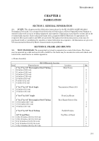
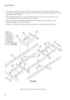
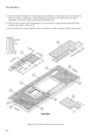
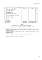
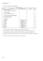
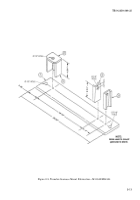
1. Cut ends of rectangular steel tubes (1, 2) at 45° angle, final length to be 96 inches (243.8 cm) and 50
inches (127.0 cm) respectively. Lay steel tubes on flat level surface in accordance with Figure 2-1. Weld
ends together. (See TM 9-237.)
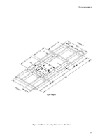
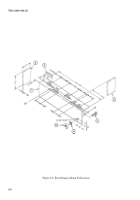
2. Lay rectangular steel tubes (3, 4, and 5) inside box frame in accordance with art in Figure 2-1 and
dimensions in Figure 2-2. Tack weld all steel tubes together.
3. Align steel angles (6 and 7) within welded framework in accordance with art in Figure 2-1 and
dimensions in Figure 2-2. Tack weld all joints.
4. Hard weld, if all items are in proper place, in accordance with welding specification QQ-A-250.
Figure 2-1. Frame Assembly Layout—Top View
Back to Top


