TB-9-2350-368-25 - Page 20 of 120
TB 9-2350-368-25
2-6
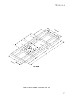
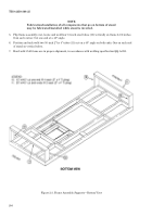
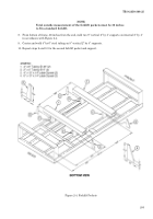
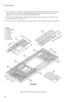
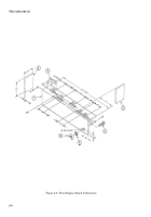
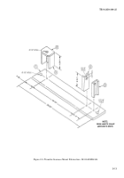
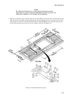
11. Cut floor plates (1 through 7) to dimensions shown in Figure 2-5. Tack weld in place as indicated in
Figure 2-4. (Items 13 through 17 on Bill of Materials list). Hard weld, if all items are in proper
alignment, in accordance with welding specification QQ-A-250.
12. Drill four holes in plate (2) for mounting the 100 amp regulator, using voltage regulator/200 amp
regulator face plate (1, Figure 2-12).
13. Test stand base may now be placed on axles and wheels or a skid according to facility requirements.
Figure 2-5. Floor Plate Dimensions and Locations
Back to Top

