TB-9-2350-368-25 - Page 28 of 120
TB 9-2350-368-25
2-14
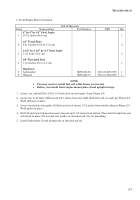
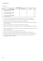
f. Engine-Only-Rear Mount
Bill Of Materials
Item
Nomenclature
Part Number
NSN
Qty
2” by 3” by 1/4” Steel Tubing
1
48 inches (121.9 cm)
1
1/2” Steel Plate
2
7-1/2 by 7-1/2 inches (19.1 by 19.1 cm)
2
Hardware
3
Cap Screw
B1821BH075C375N
6
4
Washer
MS27183-23
12
5
Nut
MS51967-23
6
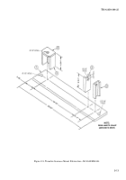
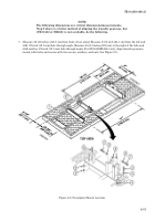
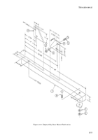
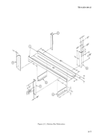
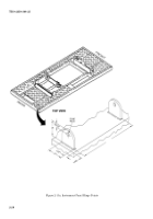
1. Drill one 3/4-inch hole, 4-1/2 inches from end of steel tubing (1) and 1-1/2 inch from the 3-inch edge
(centered). See Figure 2-9.
2. Drill one 3/4-inch hole 3-1/2 inches from the other end of steel tubing (1) and 1-1/2 inch from the 3 inch
edge (centered). See Figure 2-9.
3. Cut two 1/2-inch steel plates (2) so that the top is 2 inches and the bottom is 7-1/2 inches. See Figure 2-9.
4. Scribe a line 1-1/4 inches up from the bottom (7-1/2 inches) and another 2-3/8 inches from the side on 1/2-
inch steel plate (2). See Figure 2-9.
5. Scribe a line 4-3/4 inches up from the bottom (7-1/2 inches) and another 1-1/4 inches from the side on 1/2-
inch steel plate (2). See Figure 2-9.
6. Drill two 3/4-inch holes on 1/2-inch steel plate (2) where scribed lines intersect.
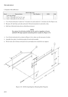
7. Bolt two brackets (1/2-inch steel plate (2)) to engine with four screws (3), washers (4), and nuts (5).
WARNING
Hanging loads can kill or injure you. Keep away from hanging
loads and overhead equipment. Keep hands out of area while
powerplant is being lifted or lowered on powerplant test stand.
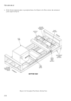
8. Install engine on powerplant test stand with 3-inch side of steel tubing (1) centered under two brackets
(2) and across powerplant test stand. Tack weld brackets (2) to 1/4-inch steel tubing (1) and tubing to
powerplant test stand. Remove engine from powerplant test stand.
9. Spot weld two brackets (2) to 1/4-inch steel tubing (1). Do not hard weld 1/4-inch steel tubing to
powerplant test stand.
10. Scribe location of two 3/4-inch holes on powerplant test stand using two holes drilled through 1/4-inch
steel tubing (1) as template.
11. Remove spot weld from powerplant test stand and 1/4-inch steel tubing (1). Remove engine only rear
mount from powerplant test stand.
12. Drill two 3/4-inch holes in powerplant test stand.
13. Install engine-only-rear mount on powerplant test stand with two screws (3), washers (4), and nuts (5).
Make corrections if necessary. Remove two screws (3), washers (4), nuts (5), and engine-only-rear mount
from powerplant test stand.
Back to Top

