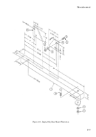
TB-9-2350-368-25 - Page 27 of 120
TB 9-2350-368-25
2-13
NOTE
The following dimensions are critical dimensions/measurements.
Step 6 above is a better method of aligning the transfer gearcase, but
if M113A2 or M548A1 is not available, do the following.
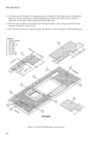
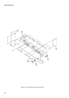
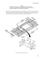
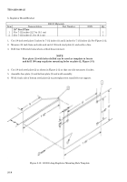
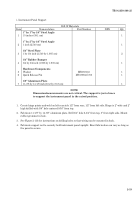
7. Measure 56-1/2 inches (143.5 cm) from front of test stand. Measure 9-1/2 inch (24.1 cm) from the left and
drill 1/2-inch (12.7 mm) hole through angle. Measure 24-3/4 inches (62.9 cm) to the right of the hole and
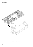
drill another 1/2-inch (12.7 mm) hole through angle. For M113A2/M548A1 only, align transfer gearcase
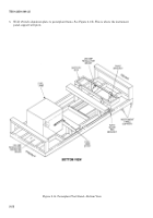
mount with holes and secure with two screws, washers, and nuts. See Figure 2-9.
Figure 2-9. Powerplant Mount Location
Back to Top

