TB-9-2350-368-25 - Page 23 of 120
TB 9-2350-368-25
2-9
c. Transmission Mount (M113A3/M548A3)
Bill Of Materials
Item
Nomenclature
Part Number
NSN
Qty
4” by 3” by 1/4” Steel Angle
1
27 inches (68.6 cm)
1
1/2” Steel Plate
2
4-1/2 by 5-1/2 inches (11.4 by 14.0 cm)
2
1/2” Rubber Pad
3
3 by 26 inches (7.6 by 66.0 cm)
1
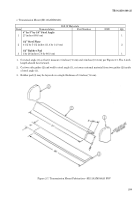
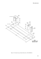
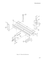
1. Cut steel angle (1) so that it measure 3 inches (7.6 cm) and 4 inches (10.2 cm) per Figure 2-7. The 3-inch
length should face forward.
2. Cut two side guides (2) and weld to steel angle (1), cut away external material from two guides (2) inside
of steel angle (1).
3. Rubber pad (3) may be layered or a single thickness of 3 inches (7.6 cm).
Figure 2-7. Transmission Mount Fabrication—M113A3/M548A3 FOV
Back to Top

