TB-9-2350-368-25 - Page 32 of 120
TB 9-2350-368-25
2-18
h. Regulator Mount/Bracket
Bill Of Materials
Item
Nomenclature
Part Number
NSN
Qty
1/8” Steel Plate
1
5 by 7-1/2 inches (12.7 by 19.1 cm)
1
2
2 by 7-1/2 inches (5.1 by 19.1 cm)
1
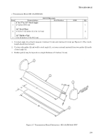
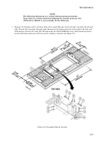
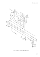
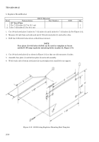
1. Cut 1/8-inch steel plate 5 inches by 7-1/2 inches (1) and 2 inches by 7-1/2 inches (2). See Figure 2-12.
2. Measure 3/4 inch from each side and end of 1/8-inch steel plate (1) and scribe a line.
3. Drill four 53/64-inch holes where scribed lines intersect.
NOTE
Face plate (1) with holes drilled can be used as template to locate
and drill 100 amp regulator mounting holes on plate (2, Figure 2-5).
4. Cut 1/8-inch steel plate (2) as shown in Figure 2-12 so that one side measures 3 inches.
5. Assemble face plate (1) and bottom plate (2) and weld assembly.
6. Weld 3-inch side of bottom steel plate (2) to powerplant test stand left rear support.
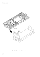
Figure 2-12. 100/200-Amp Regulator Mounting Hole Template
Back to Top

