TB-9-2350-368-25 - Page 33 of 120
TB 9-2350-368-25
2-19
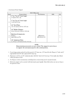
i. Instrument Panel Support
Bill Of Materials
Item
Nomenclature
Part Number
NSN
Qty
1” by 1” by 1/4” Steel Angle
1
15 inches (38.1 cm)
1
1” by 2” by 1/4” Steel Angle
2
1 inch (2.540 cm)
1
1/4” Steel Plate
3
1 by 3/4 inch (2.540 by 1.905 cm)
2
1/4” Rubber Bumper
4
3/4 by 3/4 inch (1.905 by 1.905 cm)
1
Hardware/Components
5
Washer
MS27183-6
1
6
Quick Release Pin
MS17984-C705
1
1/8” Aluminum Plate
7
11-7/8 by 14-7/8 inch (30.2 by 37.8 cm)
1
NOTE
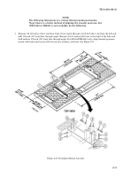
Dimension/measurements are not critical. The support is just a brace
to support the instrument panel in the raised position.
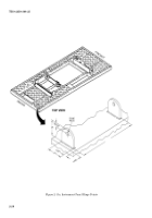
1. Create hinge points and weld on left rear side 1/2” from rear, 1/2” from left side. Hinge is 2” wide and 2”
high drilled with 3/8” hole centered 9/16” from top.
2. Fabricate 11-7/8” by 14-7/8” aluminum plate. Drill 3/4” hole 6-3/4” from top, 5” from right side. Mount
rubber grommet in hole.
3. See Figure 2-13b for instructions on drilling holes so that wiring can be mounted in back.
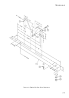
4. Fabricate support rod to securely hold instrument panel upright. Exact fabrication can vary as long as
the panel is secure.
Back to Top

