TB-9-2350-368-25 - Page 11 of 120
TB 9-2350-368-25
1-1
CHAPTER 1
INTRODUCTION
SECTION I. GENERAL INFORMATION
1-1.
PURPOSE.
The purpose of this technical bulletin is to provide general instructions for the
fabrication and operation of a powerplant test stand designed for the M113/M548 Family of Vehicles (FOV).
Although this test stand is primarily intended for the M113/M548 FOV, it can be adapted to accept all
variants of the 6V53 engine. The Opposing Forces Surrogate Vehicle (OSV) is and A3 variant that includes
the A3 engine and TX200-4/4A transmission.
Diagnostic testing, inspection, and repair of the 6V53 engine, as it applies to the M113 FOV, currently
cannot be performed at the DS/GS level without first installing the powerpack in the vehicle. Many hours
can be wasted installing a powerpack, only to find it faulty. Preventive Maintenance, Checks, and Services
(PMCS) and troubleshooting procedures found in the respective operator’s and unit maintenance manuals
apply as if the system were installed in the vehicle. To insure safety, reference to the appropriate manuals is
mandatory.
SECTION II. DESCRIPTION AND DATA
1-2.
COMPONENTS.
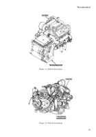
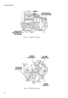
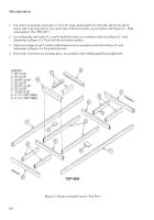
The majority of the parts and fabricated components for the M113 powerplant test
stand are listed in TM 9-2350-277-24P and can be procured from that source. However, these parts and
fabricated components are suggestions and they may be procured locally or replaced with similar materials.
This test stand may be mounted on wheels or a pallet configuration according to the user requirements. The
air intake system needs to be covered to protect personnel from danger, therefore a guard has been used. If
preferred, the M113A2 air intake system can be adapted for use. The same applies for the exhaust system.
Exhaust elbows have been added to direct exhaust heat away from personnel.
The M113A3 FOV is equipped with a glow plug cold weather starting system. The glow plug indicator light is
found in center of instrument panel on right side. Troubleshoot using applicable TM series.
1-3.
CAPABILITIES.
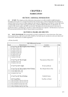
The powerplant test stand is equipped with the capabilities and service test
options normally found at all maintenance levels for the M113A2, M548A1, M113A3, M548A3 vehicles. The
powerplant test stand can store 10 to 20 gallons of DF2-DF1 and JP8 fuel. It has a self-contained 24-volt
electrical system using four 6 TL batteries connected in parallel series. It can isolate problems to a particular
circuit using four circuit breakers. Select any transmission range (1-2, 1-3, 1-4, PV, R, SL) by using a
fabricated/standard electrical transmission controller (M113A3 and M548A3 only). The M113A2 and
M548A1 uses the transmission selector lever which is mounted on the transmission. The powerplant test
stand is equipped with charging system regulators for both the 100-amp and 200-amp generators. The
powerplant test stand is equipped with most of the capabilities normally found on the M113/M548 FOV
instrument panel such as: master switch indicator, transmission filter clogged indicator, transmission high
oil temperature indicator, transmission low oil pressure indicator, fuel gauge, battery generator indicator
gauge, starter switch, air box heater switch, and glow plug light indicator. The test stand has the following
systems installed and the ability to perform stall checks and other on-line tests. This powerplant test stand
can be adapted to feed many types of powerpacks using 6V53 engine.
Back to Top

