TB-9-2920-225-34-1 - Page 44 of 70
TB 9-2920-225-34-1
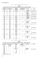
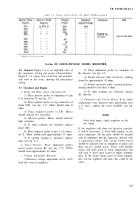
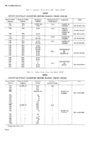
Table 3–2. Voltage Checks (Power On—Model 5027RA-continued
Section III. LEECE-NEVILLE MODEL R0015027RB
3-6. General.
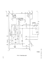
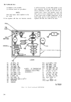
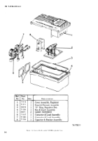
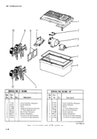
Figure 3–6 is an exploded view of
the regulator, listing the major subassemblies.
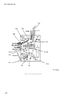
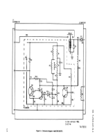
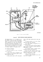
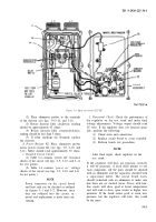
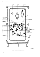
Figure 3–7 is a plan view of the box and an under-
side view of the cover, showing the interconnect
wiring.
3-7. Checkout and Repair.
a. Diode and Relay (power disconnected).
(1) Place positive probe of ohmmeter to pin
F of connector J2 (see fig. 3-7).
(2) Place negative probe to top connection of
diode CR2, (see fig. 3–7). Meter should read O
ohms.
(3) Place negative probe to TP1. Meter
should indicate low resistance.
(4) Reverse probes. Meter should indicate
high resistance.
(5) If other readings are obtained, replace
diode
CR2.
(6) Move negative probe to pin C of connec-
tor J1. Meter should read approximately 55 ohms.
(7) If another reading is obtained, replace
relay (see fig. 3–7).
b. Power Resistor.
Place ohmmeter probes
across power resistor R1 (see fig.
should read approximately 40 ohms.
c. Voltage Adjustment Rheostat.
(1)
Remove voltage adjustment
from the cover of regulator.
3–7). Meter
access screw
(2) Place ohmmeter probes to terminals of
the rheostat (see fig. 3-7).
(3) Rotate rheostat fully clockwise, reading
shoud be approximately 45 ohms.
(4) Rotate rheostate fully counterclockwise,
reading should be less than 5 ohms.
(5) If other readings are obtained, replace
the rheostat.
d. Transistor and Circuit Board.
If no faulty
components were detected after performing tests
a, b, and c, replace the cover assembly (see fig.
3-7) .
NOTE
After final repair, check regulator on the
test stand.
If the regulator still does not function correctly
it will be necessary, if local skills permit, to test
each component. All the parts should be checked
with an ohmmeter and the capacitors checked with
a capacitance meter. The circuit board traces
should be checked with an ohmmeter to make sure
there are no cracked traces. Traces with hairline
cracks will show good at lower temperatures and
will tend to show open circuit at higher tempera-
tures. If the board seems good at room tempera-
ture, but the regulator still fails, this could be the
cause.
3-7
Back to Top

