TB-9-2920-225-34-1 - Page 46 of 70
TB 9-2920-225-34-1
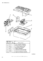
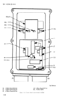
Figure 3-7. 0pen view–model 5027RB.
Section IV.
LEECE-NEVILLE MODEL R0015027RC
3-8. General.
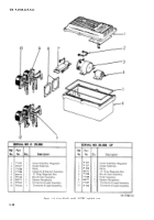
Figure 3–8 is an exploded view of
the regulator, listing the major subassemblies.
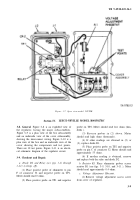
Figure 3–9 is a plan view of the box subassembly
and an underside view of the cover subassembly,
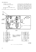
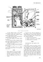
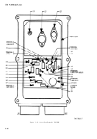
showing the interconnect wiring. Figure 3–10 is a
plan view of the box and an underside view of the
cover showing the components and test points.
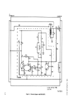
There are 10 test points. Figure 3–11 is an electri-
cal schematic diagram of the regulator circuit.
3-9. Checkout and Repair.
a. Diode D2 and Relay (see jigs. 3–8 through
3–11) (voltage off).
(1) Place positive probe of ohmmeter to pin
F of connector J2 and negative probe on TP1.
Meter should read 0 ohms.
(2) Place positive probe on TP1 and negative
probe on TP2. Meter should read low ohms (hun-
dreds ).
(3) Reverse probes in (2) above. Meter
should read high ohms (thousands).
(4) If other readings are obtained in (2) or
(3), replace diode D1.
(5) Place positive probe on TP2 and negative
probe on pin C of connector J2. Meter should read
approximately 55 ohms.
(6) If another reading is obtained, remove
and replace both the relay and diode D2.
b. Resistor R1.
Place ohmmeter probes across
resistor R1 (see figs. 3-9, 3-10, and 3–11 ), Meter
should read approximately 0.4 ohms.
c. Voltage Adjustment Rheostat.
(1)
Remove voltage adjustment access screw
from cover of regulator.
3-9
Back to Top

