TB-9-2920-225-34-1 - Page 61 of 70
TB 9-2920-225-34-1
d. Transistors.
NOTE
Transistors Q4 and Q5 can be checked
fairly accurately without removing them
from the circuit.
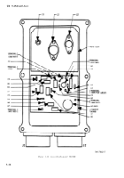
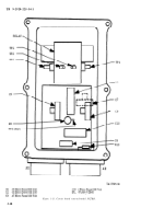
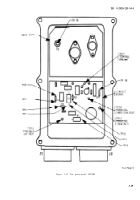
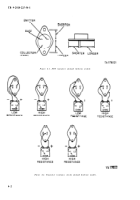
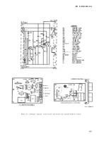
(1) Check transistors Q4 and Q5, (see fig.
4-3), inaccordance with figures 4-l and 4-2.
NOTE
Due to the connection
cuit, omit the emitter
in figure 4-2.
(2) If other readings
transistors Q4 and Q5.
of Q4 in the cir-
to collector check
are obtained, replace
e. Circuit Board.
If no faulty components were
detected after performing tests a, b, and c, replace
the circuit board.
f. Functional Check.
Check the performance of
the regulator on the test stand and make final
voltage adjustments. Voltage output should read
28 volts. If the regulator does not function prop-
erly, perform the following:
(1) Check wires and connections.
(2) Replace circuit board.
(3) Perform bench test procedures.
NOTE
After final repair, check regulator on the
test stand.
If the regulator still does not function correctly it
will be necessary, if local skills permit, to test
each component. All the parts should be checked
with an ohmmeter and the capacitors checked with
a capacitance meter. The circuit board traces
should be checked with an ohmmeter to ensure
that there are no cracked traces. Traces with hair-
line cracks will show good at lower temperatures
and will tend to show open circuit at higher tem-
peratures. If the board seems good at room tem-
perature, but the regulator still fails, this could
be the cause.
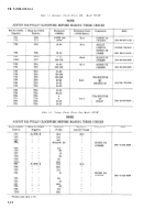
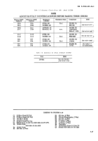
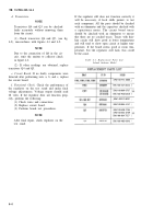
Table 4-1. Replacement Parts List-
Leland Airborne Model
4-4
Back to Top

