TB-9-2920-225-34-1 - Page 62 of 70
TB 9-2920-225-34-1
CHAPTER 5
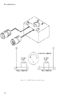
100 AMP REGULATOR CHECKER
5-1. Purpose.
This checker is intended to provide
quick bench tests to determine the general condi-
tion f the regulator. The checker is not intended
to replace the authorized test stands which are
necessary to determine the accurate operating
condition of the regulator.
5-2. Construction.
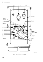
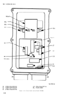
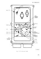
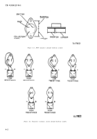
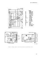
The regulator checker can be
locally fabricated using salvaged components. The
mini-ammeter is an optional feature and most any
meter can be used, provided it is shunted to give
midscale reading.
5-3. Power Supply.
The regulator checker is used
in conjunction with a variableexternal power sup-
ply having the following characteristics:
a.
Voltage range 0-32 volts DC minimum.
b.
Current range must be at least 2 AMPS.
c.
The output power must be well filtered.
NOTE
The 500 AMP test stands, external power
supply is adequate if additional filtering
is added.
5-4. Operation.
a.
Connect the checker to the regulator to be
tested.
b.
Connect power supply to the checker.
CAUTION
Be sure proper polarity is maintained.
c.
Advance the power supply voltage control
and note the voltage when the regulator relay is
closed and the main circuit light comes on. This
is the relay closing voltage.
d.
Advance the voltage to 20 volts. The field
indicator light should come on if the regulator
switching transistors are functioning.
e.
Advance the voltage until the field light turns
off (maximum of 32 volts). The light should shut
off if the regulating and switching transistors are
functioning correctly.
f.
Adjust the power supply voltage to
adjust the regulator voltage adjusting
until the field indicator light turns off.
g.
If the regulator fails these checks,
bench tests and repairs.
28
volts,
rheostat
perform
h.
If the regulator passes these checks, perform
final tests on the authorized test stand.
5-5. Mini-Ammeter Operation.
If the regulator
checker is equipped with the optional meter, the
following additional data can be obtained.
a.
Note the average regulator current draw
from several regulators which are known to be in
good operating condition.
b.
While performing the above, check if the
meter reading is higher than normal, check for
shorted components and circuit. If the reading is
lower than normal, check for open circuits and
components.
5-1
Back to Top

