TB-9-3950-253-13-P
PALLETIZED LOAD SYSTEM TRUCK, M1075 and M1075A1 (PLS) AND HEAVY EXPANDED MOBILITY TACTICAL TRUCK, M1120, M1120A2, AND M1120A4 (HEMTT), ENHANCED CONTAINER HANDLING UNIT (E-CHU)
TECHNICAL BULLETIN; OPERATOR AND FIELD MAINTENANCE, INSTALLATION INSTRUCTIONS, AND REPAIR PARTS AND SPECIAL TOOLS LIST
JULY 2009
TB-9-3950-253-13-P - Page 298 of 704
TB 9-3950-253-13&P
Change 1
0029-16
0029
REMOVAL – CONTINUED
Relay Box Wiring Removal
00029
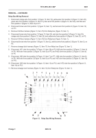
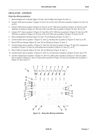
1. Disconnect orange wire from position 1 (Figure 13, Item 19), yellow wire from position 2 (Figure 13, Item 20),
green wire from position 3 (Figure 13, Item 21), blue wire from position 4 (Figure 13, Item 22), and lilac wire
from position 7 (Figure 13, Item 23) on P1.
2. Disconnect brown wire from position 1 (Figure 13, Item 11), and red wire from position 2 (Figure 13, Item 12)
on P11.
3. Remove CAN bus harness (Figure 13, Item 15) from Relay box (Figure 13, Item 1).
4. Disconnect brown wire from position 1 (Figure 13, Item 24), red wire from position 2 (Figure 13, Item 25),
orange wire from position 3 (Figure 13, Item 26), and yellow wire from position 4 (Figure 13, Item 27), on P2.
5. Remove CAN bus harness (Figure 13, Item 18) from Relay box (Figure 13, Item 1).
6. Disconnect brown wire from position 1 (Figure 13, Item 2), and blue wire from position 2 (Figure 13, Item 3), on
P3.
7. Remove stowage latch harness (Figure 13, Item 17) from Relay box (Figure 13, Item 1).
8. Disconnect 1471 wire from position 7 (Figure 13, Item 28) on P2,1466 wire from position 2 (Figure 13, Item 4)
on P4, 1469 wire from position 2 (Figure 13, Item 5) on P5, and 1462 wire from position 2 (Figure 13, Item 6)
on P6.
9. Disconnect 1463 wire from position 2 (Figure 13, Item 7) on P7, 1464 wire from position 2 (Figure 13, Item 8)
on P8, 1468 wire from position 2 (Figure 13, Item 9) on P9, and 1467 wire from position 2 (Figure 13, Item 10)
on P10.
10. Disconnect 1435 wire from position 1 (Figure 13, Item 13) on P12, and 1472 wire from position 2 (Figure 13,
Item 14) on P12.
11. Remove stowage loom harness (Figure 13, Item 16) from Relay box (Figure 13, Item 1).
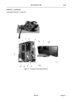
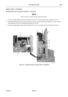
Figure 13.
Relay Box Wiring Removal.
0029
2
3
4
5
7
8
9
10
11
12
13
14
15
16
17
18
19
20
21
22
23
24
25
26
27
28
1
6
Back to Top

