TB-9-3950-253-13-P
PALLETIZED LOAD SYSTEM TRUCK, M1075 and M1075A1 (PLS) AND HEAVY EXPANDED MOBILITY TACTICAL TRUCK, M1120, M1120A2, AND M1120A4 (HEMTT), ENHANCED CONTAINER HANDLING UNIT (E-CHU)
TECHNICAL BULLETIN; OPERATOR AND FIELD MAINTENANCE, INSTALLATION INSTRUCTIONS, AND REPAIR PARTS AND SPECIAL TOOLS LIST
JULY 2009
TB-9-3950-253-13-P - Page 33 of 704
0003-1/(2 Blank)
Change 1
0003
TB 9-3950-253-13&P
OPERATOR AND FIELD MAINTENANCE
-
THEORY OF OPERATION
INTRODUCTION
0003
The Enhanced-Container Handling Unit (E-CHU) is a kit for the PLS M1075 and M1075A1 or HEMTT LHS M1120,
M1120A2, and M1120A4 that allows the vehicle to load, transport, and unload 20 ft long ISO containers.
DESCRIPTION
0003
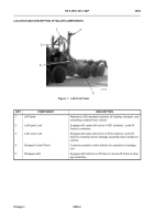
1. The E-CHU consists of three main assemblies: the stowage unit, lift frame, and roller assembly.
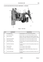
a. Stowage Unit:
(1) The stowage unit is installed forward of the compression frame and is used to secure the lift frame
while a container is not loaded on the vehicle.
(2) The stowage unit unloads the lift frame enabling the vehicle’s Load Handling System (LHS) to engage
the lift frame at the bail bar and position the lift frame on the end of an ISO container.
(3) The transport locks on the stowage unit secure the lower-front corner castings while a container is
loaded on the vehicle.
b. Lift Frame:
(1) The lift frame is stored on the stowage unit when not deployed on an ISO standard container.
(2) When deployed, the lift frame locks onto the upper and lower corner castings of the container enabling
the LHS of the truck to load and unload the container.
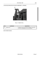
(3) The bail bar lock secures the lift frame on the hook preventing the lift frame from disengaging.
c.
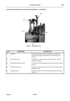
Slider Assembly:
(1) The slider assembly is installed at the rear of the truck and aligns, centers, and supports the container
during loading and unloading operations.
(2) Two Twistlock modules on the rear of the slider assembly lock the lower-rear corner castings of the
container into place for transport.
(3) The slider assembly can be configured by the operator for either flatrack or container operation.
2. The E-CHU includes Automatic Mode Sensors and Lockout Sensors.
a. The Automatic Mode Sensors are located on the hook arm and the middle frame. They sense the position
of the LHS during loading/unloading and adjust the loci path, keeping the lift frame clear of the rear slider
assembly.
b. Lockout Sensors are located in the twistlock modules on the slider assembly and in the transport locks on
the stowage unit. These sensors detect the status of the twistlocks and transport locks. All unloading
functions are stopped if any of the locks are not in the stowed position or still engaged in the container.
END OF WORK PACKAGE
2
Back to Top

