TM-1-1730-227-13-P - Page 58 of 138
0016 00
TM 1-1730-227-13&P
REPAIR OR REPLACEMENT – CONTINUED
2.
Use the appropriate hand file contained in the tool kit to remove burrs and sharp edges from trailer undercar-
riage.
3.
Tighten loose parts. Replace missing, damaged, bent or distorted parts.
DISASSEMBLY
1.
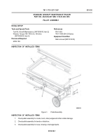
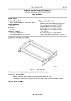
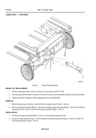
Remove four hex head cap screws (Figure 1, Item 9) with lock washers (Figure 1, Item 8) securing the pintle
hook (Figure 1, Item 1) to the trailer undercarriage (Figure 1, Item 10). Remove the pintle hook (Figure 1,
Item 1).
2.
Remove four spring pins (Figure 1, Item 7), two king pins (Figure 1, Item 3), two flat washers (Figure 1, Item 6)
and two thrust washers (Figure 1, Item 4) securing the left and right hand axle and king pin pivot assemblies
(Figure 1, Item 5 and 11) to the trailer undercarriage. Remove both left and right hand axle and king pin pivot
assemblies (Figure 1, Item 5 and 11).
3.
Unscrew four tie-down rings (Figure 1, Item 2) from the front and rear of the trailer undercarriage (Figure 1,
Item 10).
ASSEMBLY
1.
Screw four tie-down rings (Figure 1, Item 2) into position on the front and rear of the trailer undercarriage
(Figure 1, Item 10) until tight.
2.
Install the left and right hand axle and king pin pivot assemblies (Figure 1, Item 5 and 11) into position with
two thrust washers (Figure 1, Item 4), two flat washers (Figure 1, Item 6), two king pins (Figure 1, Item 3) and
four spring pins (Figure 1, Item 7).
3.
Position the pintle hook (Figure 1, Item 1) on the rear of the trailer undercarriage (Figure 1, Item 10) and
install four hex head cap screws (Figure 1, Item 9) with lock washers (Figure 1, Item 8). Tighten hex head cap
screws (Figure 1, Item 9) to a torque of
540 in-lbs
.
END OF WORK PACKAGE
0016 00-2
Back to Top

