TM-5-2330-378-14-P - Page 170 of 524
TM5-2330-378-14&P
4-35. VOLTAGEREDUCTIONBOXREPLACEMENT(M870)(continued).
5.
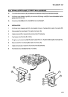
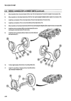
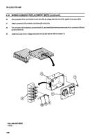
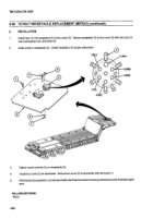
Remove two screws (7), washers (8), and nuts (9) from voltage reduction box (2).
6.
Remove conduit fitting locknut (10) from conduit fitting (111).
7.
Remove voltage reduction box (2) from frame member (12).
12
9
11
2
8
10
b.
INSTALLATION
I
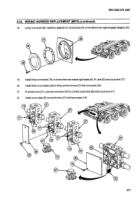
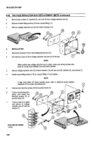
Remove six screws (1) from new voltage reduction box (2).
2.
Pull new box cover (3) from voltage reduction box and out of the way.
7
NOTE
When putting new voltage reduction box in place, make sure wiring harness wire
ends do not get stuck between box and frame member.
3.
Secure voltage reduction box (2) to frame member (12) with two nuts (9), washers (8), and screws (7).
4.
Install conduit fitting locknut (10) on conduit fitting (111)and tighten.
NOTE
If tags have fallen off wiring harness wires, refer to electrical wiring diagram
(Appendix K) for proper wire placement.
5.
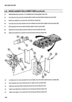
Remove four terminal screws (4) from junction block (5).
6.
Put
four circuit
wires (6) in
12
2
place,
and install four
9
terminal screws (4) on
a
junction block (5).
7.
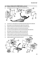
Put box cover (3) in place
and secure
to voltage
reduction box (2) with six 3
screws (1).
10
10 0
7
*eQV1`
(@'@
I
-
4
FOLLOW-ON
TASKS:
- None
6
4-82
Back to Top

