TM-5-2350-262-20-3 - Page 47 of 319
3-12
TM 5-2350-262-20-3
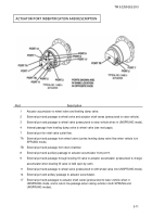
Rotary actuator shaft:
(mounts roadwheel arm)
Relief valve:
Protects unit from
high- pressure surges
TYPICAL NO. 1 AND 4 ACTUATOR SCHEMATIC DIAGRAM
Dampening valve:
Permits free flow into accumulators
so they can rapidlyabsorb suspension
shocks, but restricts flow rate from
accumulators to provide smooth
reaction to suspension shocks
Wheel accumulators:
Attach to port 1 of rotary actuator,
function as suspension springs when
vehicle is in SPRUNG mode
Leveling dump valve:
Opened by cam to drain
accumulators and lower
vehicle when vehicle is too
high
Cam:
Bolted to actuator shaft, opens
and closes leveling valves at
appropriate points of shaft
rotation (at appropriate vehicle
height)
Leveling fill valve:
Opened by cam to replenish
accumulators and raise
vehicle when vehicle is too
low
Shock load and replenishing check valve:
Permits replenishing of accumulator via port 9, but
prevents accumulator pressure surges from entering
circuit No. 9
x
x
Ports 11, 17, 2 and 3 are plugged on
LH or RH side of unit, depending on
desired direction of shaft rotation.
When plugs are installed as shown,
pressure to port 2 will cause clockwise
shaft rotation
Wheel valve:
A. In SPRUNG mode (shown),
actuator shaft is hydraulically
connected to accumulators
(suspension has springs), and flow
from leveling dump valve can
return to reservoir through port
7A
B. In UNSPRUNG mode (port 11
pressurized), actuator shaft is
isolated from accumulator
(suspension has no springs), flow
from leveling dump valve is
blocked to prevent loss of
accumulator pressure during
dozing, and actuator shaft is
hydraulically connected to main
control valve via port 3
Back to Top

