TM-5-2350-377-13-P - Page 17 of 404
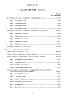
TABLE OF CONTENTS - Continued
Page No.
WP Sequence No.
Table 2. Control Box Connector Pins.
.........................................................................................
0012-6
Figure 6. Control Box Connectors J-1 and J-2.
...........................................................................
0012-7
Table 3. Control Box Left Side Tension Switch.
..........................................................................
0012-7
Table 4. Control Box Right Side Tension Switch.
........................................................................
0012-
8
Figure 7. Track Loosening Switch.
..............................................................................................
0012-
9
Table 5. Control Box Track Loosening Switch.
............................................................................
0012-9
Figure 8. Track Loosening Switch.
............................................................................................
0012-10
Table 6. Control Box Switch Tests.
............................................................................................
0012-11
Figure 9. Control Box Wiring Harness.
......................................................................................
0012-12
Table 7. Control Box Switch Test.
.............................................................................................
0012-13
Figure 10. Control Box Wiring Harness.
....................................................................................
0012-14
Table 8. Control Box Switch Tests.
............................................................................................
0012-15
TROUBLESHOOTING PROCEDURES - TRACK (LEFT OR RIGHT) WILL NOT TIGHTEN
OR LOOSEN, TRACK ADJUSTING CYLINDER.
....................................................................
WP 0013
Figure 1. Oil Flow Test.
................................................................................................................
0013-3
Figure 2. Hose Test.
....................................................................................................................
0013-4
TROUBLESHOOTING PROCEDURES - FRONT CORNER (LEFT OR RIGHT) DOES NOT
RAISE OR LOWER IN UNSPRUNG MODE, TRACK ADJUSTING CYLINDER.
.....................
WP 0014
Figure 1. Track Adjusting Cylinders Manifold.
.............................................................................
0014-3
Figure 2. Hose Test.
....................................................................................................................
0014-4
TROUBLESHOOTING PROCEDURES - LEFT OR RIGHT TRACK ADJUSTING CYLINDERS
WILL NOT EXTEND AFTER SUSPENSION CONTROL LEVERS ARE RETURNED
TO NEUTRAL.
...........................................................................................................................
WP 0015
Figure 1. Track Adjusting Cylinders Manifold.
.............................................................................
0015-3
Figure 2. Hose Test.
....................................................................................................................
0015-4
TROUBLESHOOTING PROCEDURES - BLADE WILL NOT FOLD OR UNFOLD
IN SPRUNG MODE.
..................................................................................................................
WP 0016
Figure 1. Test Spool Valve.
.........................................................................................................
0016-2
Figure 2. Hose Test.
....................................................................................................................
0016-4
TM 5-2350-377-13&P
v
Back to Top


