TM-5-2350-377-13-P - Page 25 of 404
TABLE OF CONTENTS - Continued
Page No.
WP Sequence No.
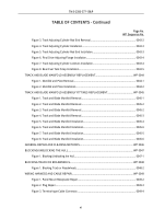
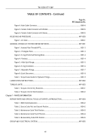
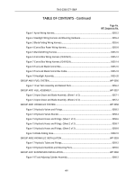
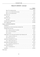
Figure 1 Apron Wiring Harness.
..................................................................................................
0055-2
Figure 2 Headlight Wiring Harness and Mounting Hardware.
.....................................................
0055-4
Figure 3 Blade Folding Wiring Harness.
......................................................................................
0055-6
Figure 4 Control Box Power Wiring Harness.
..............................................................................
0055-8
Figure 5 Manifold Wiring Harness.
............................................................................................
0055-10
Figure 6 Control Box Wiring Harness.(12491623).
....................................................................
0055-12
Figure 7 Control Box Wiring Harness.(12491624).
....................................................................
0055-14
Figure 8 Track and Blade Control Box.
......................................................................................
0055-16
Figure 9 Track and Blade Control Box Cable.
...........................................................................
0055-18
Figure 10 Headlight Assembly.
..................................................................................................
0055-20
GROUP AM01 FUEL SYSTEM.
..........................................................................................................
WP 0056
Figure 11 Fuel Tank Assembly and Related Parts.
.....................................................................
0056-2
GROUP AP01 HULL ASSEMBLY.
......................................................................................................
WP 0057
Figure 12 Apron Dozer and Blade Assembly. (Sheet 1 of 2) .
.....................................................
0057-1
Figure 12 Apron Dozer and Blade Assembly. (Sheet 2 of 2) .
.....................................................
0057-2
GROUP AR01 HYDRAULIC SYSTEM.
..............................................................................................
WP 0058
Figure 13 Hydraulic Valves and Fittings.
.....................................................................................
0058-2
Figure 14 Hydraulic Valves Bracket.
............................................................................................
0058-4
Figure 15 Hydraulic Hoses and Fittings. (Sheet 1 of 3) .
.............................................................
0058-6
Figure 15 Hydraulic Hoses and Fittings. (Sheet 2 of 3) .
.............................................................
0058-7
Figure 15 Hydraulic Hoses and Fittings. (Sheet 3 of 3) .
.............................................................
0058-8
Figure 16 Blade Folding Hose.
..................................................................................................
0058-10
GROUP AR02 HYDRAULIC INSTALLATION.
....................................................................................
WP 0059
Figure 17 Hydraulic Tubes and Fittings.
......................................................................................
0059-2
Figure 18 Hydraulic Manifolds and Mounting Parts.
....................................................................
0059-6
GROUP A301 SUSPENSION INSTALLATION.
.................................................................................
WP 0060
Figure 19 Track Adjusting Cylinder Assembly.
............................................................................
0060-2
TM 5-2350-377-13&P
xiii
Back to Top

