TM-5-2350-377-13-P - Page 22 of 404
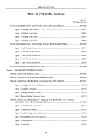
TABLE OF CONTENTS - Continued
Page No.
WP Sequence No.
HYDRAULIC VALVES REPLACEMENT.
..........................................................................................
WP 0039
Figure 1. Flow Valve Bodies Removal.
........................................................................................
0039-1
Figure 2. Flow Valves Removal.
..................................................................................................
0039-2
Figure 3. Flow Valves Installation.
...............................................................................................
0039-3
HYDRAULIC FITTINGS REPLACEMENT.
........................................................................................
WP 0040
Figure 1. Flow Valves Removal.
..................................................................................................
0040-1
Figure 2. Flow Valves Installation.
...............................................................................................
0040-2
HYDRAULIC INTERMEDIATE MANIFOLD AND FITTINGS REPLACEMENT (LEFT SIDE).
..........
WP 0041
Figure 1. Intermediate Manifold Removal.
...................................................................................
0041-3
Figure 2. Manifold Tubes Removal.
.............................................................................................
0041-3
Figure 3. Manifold Tubes Removal.
.............................................................................................
0041-4
Figure 4. Manifold Tubes Installation.
..........................................................................................
0041-5
Figure 5. Manifold Tubes Installation.
..........................................................................................
0041-
7
Figure 6. Manifold Tubes Installation.
..........................................................................................
0041-7
HYDRAULIC HOSES REPLACEMENT.
............................................................................................
WP 0042
Figure 1. Blade Folder and Apron Hoses Removal.
....................................................................
0042-1
Figure 2. Blade Folder Hose Clamps Removal.
..........................................................................
0042-2
Figure 3. Blade Folder Hose Clamps on Hull Plate Removal.
.....................................................
0042-2
Figure 4. Blade Folder Hoses and Flow Valves Removal.
..........................................................
0042-3
Figure 5. Blade Folder Hoses Removal.
......................................................................................
0042-3
Figure 6. Blade Folder Hoses and Flow Valves Installation.
.......................................................
0042-4
Figure 7. Blade Folder Hose Clamps Installation.
.......................................................................
0042-5
Figure 8. Blade Folder Hose Clamps Installation.
.......................................................................
0042-5
Figure 9. Blade Folder and Apron Hoses Installation.
.................................................................
0042-6
TRACK ADJUSTING CYLINDER ASSEMBLY REPLACEMENT.
.....................................................
WP 0043
Figure 1. Rear Fuel Tank Strap Removal.
...................................................................................
0043-1
Figure 2. Final Drive Adjusting Flange Removal.
........................................................................
0043-2
TM 5-2350-377-13&P
x
Back to Top

