TM-5-2350-377-13-P - Page 21 of 404
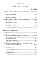
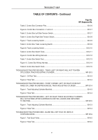
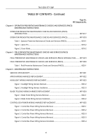
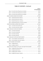
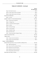
TABLE OF CONTENTS - Continued
Page No.
WP Sequence No.
Figure 13. Inner Bushings from Apron Disassembly.
................................................................
0036-1
2
Figure 14. Rubber Pad and Plate Repair.
..................................................................................
0036-1
3
Figure 15. Installation of Bushings onto Apron Assembly.
........................................................
0036-1
3
Figure 16. Ripper Blade and Apron Assembly.
..........................................................................
0036-1
5
Figure 17. Installation of Studs onto Apron Assembly.
..............................................................
0036-1
6
Figure 18. Cutting Edges Assembly.
.........................................................................................
0036-1
7
Figure 19. Apron and Dozer Extensions Assembly.
..................................................................
0036-1
8
Figure 20. Alignment of Apron and Dozer Assembly.
................................................................
0036-1
9
Figure 21. Apron Wear Plates and Side Seals Assembly.
.........................................................
0036-
20
Figure 22. Apron Strips Assembly.
............................................................................................
0036-
21
Figure 23. Apron and Dozer Assembly Installation.
...................................................................
0036-2
2
Figure 24. Installation of Apron onto Hull.
..................................................................................
0036-2
3
Figure 25. Hydraulic Cylinders Installation.
...............................................................................
0036-2
3
Figure 26. Headlight Intermediate Wiring Harness and Apron Wiring Harness Installation.
.....
0036-2
4
DOZER BLADE REPLACEMENT AND REPAIR.
..............................................................................
WP 0037
Figure 1. Inner Pivot Pins Removal.
............................................................................................
0037-1
Figure 2. Outer Pivot Pins Removal.
...........................................................................................
0037-2
Figure 3. Shackle and Dozer Blade Disassembly.
.......................................................................
0037-3
Figure 4. Shackle and Dozer Blade Assembly.
...........................................................................
0037-3
Figure 5. Pivot Points Installation.
...............................................................................................
0037-4
Figure 6. Dozer Blade Installation.
...............................................................................................
0037-5
Figure 7. Chain Connection.
........................................................................................................
0037-5
Figure 8. Dozer Blade and Pin Assembly Installation.
.................................................................
0037-6
Figure 9. Inner Pivot Pins Installation.
.........................................................................................
0037-7
ACTUATOR ASSEMBLY REPLACEMENT.
......................................................................................
WP 0038
Figure 1. Apron Actuator Removal.
.............................................................................................
0038-1
Figure 2. Apron Actuator Installation.
..........................................................................................
0038-2
TM 5-2350-377-13&P
ix
Back to Top

