TM-5-2350-377-13-P - Page 229 of 404
FIELD MAINTENANCE
TRACK AND BLADE MANIFOLD ASSEMBLY FITTINGS REPLACEMENT
INITIAL SETUP:
Tools and Special Tools
Tool Kit, General Mechanic's: Automotive
(WP
0071, Table 1, Item 7)
Parts Kit, Hydraulic (WP
0071, Table 1, Item 4)
Materials/Parts
Lubricating Oil, Engine OE/HDO-10
(WP
0070, Table 1, Item 18, 19, 20)
Cleaning Compound, Solvent
(WP
0070, Table 1, Item 6)
Personnel Required
Construction Equipment Repairer, 91L
Equipment Condition
Right, center, and left rear floor plates removed
(TM 5-2350-262-10)
Hydraulic system pressure relieved
(TM
2350-262-20)
Hydraulic hoses removed (WP
0042)
REMOVAL
1.
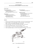
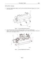
Remove ten control box power harness connectors (Figure 1, Item 2) from coil connectors (Figure 1, Item 1).
2.
Remove tee (Figure 1, Item 7), reducer (Figure 1, Item 8), and tee (Figure 1, Item 9) from elbow
(Figure
1,
Item
6) on track and blade manifold (Figure 1, Item 3), port T.
3.
Remove elbow (Figure 1, Item 6) from track and blade manifold (Figure 1, Item 3), port P.
4.
Remove two straight adapters (Figure 1, Item 4) from tee (Figure 1, Item 5).
5.
Remove tee (Figure 1, Item 5) from track and blade manifold (Figure 1, Item 3), port BR.
6.
Remove straight adapter (Figure 1, Item 4) from track and blade manifold (Figure 1, Item 3), port BL.
6
M0081HBF
5
4
3
1
2
9
8
7
6
Figure 1.
Track and Blade Manifold Removal.
TM 5-2350-377-13&P
0045
0045-1
Back to Top


