TM-5-2350-378-24-P - Page 264 of 790
TM 5--2350--378--24&P
FRONT CORNER (LEFT OR RIGHT) RAISES IN SPRUNG, BUT NOT UNSPRUNG MODE --
Continued
0013 00
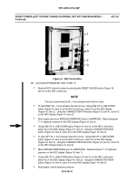
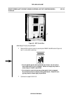
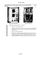
Figure 21. HDC Control Box
Figure 22. DCV Bank
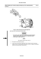
Figure 23. Main Relief Valve
MAIN RELIEF VALVE ADJUSTMENT -- CONTINUED
Disable ejector by manually closing the ejector inhibit ball valve V23 (Figure 22, item 1)
on the DCV bank. Using LINE UP or LINE DOWN button (Figure 21, item 3), select V1
on the HDC display (Figure 21, item 2). Close V1 on the HDC display (Figure 21,
item 2) by selecting the CHANGE POSITION button (Figure 21, item 4) on the HDC
control box.
With SPRUNG/UNSPRUNG lever in SPRUNG, have assistant move left hand
SUSPENSION CONTROL lever to RAISE, while at the same time, holding EJECTOR
CONTROL lever in BACK. Observe transducer T--4 hydraulic pressure on the HDC
display (Figure 21, item 1). If pressure is not within limits adjust the main relief valve
13L by loosening jam nut (Figure 23, item 2) and rotating adjustment screw (Figure 23,
item 1) clockwise to increase pressure; counter clockwise to decrease pressure. When
hydraulic pressure is within limits, tighten jam nut (Figure 23, item 2).
Continued on page 0013 00--41.
0013 00--39/40 blank
Back to Top


