TM-5-2350-378-24-P - Page 30 of 790
TM 5--2350--378--24&P
0004 00--5
INTRODUCTION TO TROUBLESHOOTING AND REPAIR OF THE M9 ACE HYDRAULIC
SYSTEM -- Continued
0004 00
HYDRAULIC SYSTEM -- CONTINUED
Hydraulic High--Pressure Filters
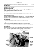
Two high--pressure filters located directly in front of the driver’s compartment, filter hydraulic fluid from the main
hydraulic pump while it is enroute to the directional control valve bank.
Hydraulic Reservoir
The hydraulic reservoir is located beneath the driver’s compartment and its check and fill point is located in the
driver’s compartment. It has a capacity of 32 gal. (121 L) of OE/HDO--10.
Direction Control Valve (DCV) Bank
The control valve bank is located beneath the hydraulic high--pressure filters. The control valves in the valve bank
are activated by mechanical linkages from the operator’s compartment and they, in turn, activate the hydraulic
functions of the vehicle.
Hydraulic Manifolds
Located in the hull, the manifolds route the flow of hydraulic fluid to the vehicle components.
Compensating Hydraulic Pump
Located on the front of the transfer case, the pump provides pressure at a constant 2,800--2,900 psi
(19,306--19,996 kPa) to the SPRUNG/UNSPRUNG hydraulic operation. Capacity of this variable displacement
pump is 10 gpm (38 Lpm).
Main Hydraulic Pump
A fixed displacement pump is mounted on the rear of the transfer case. The pump pulls fluid from the hydraulic
reservoir and circulates it through the hydraulic filters at 13 gpm (49 Lpm), then splits the pressure at the
directional control valves to provide pressure to both left and right suspension controls.
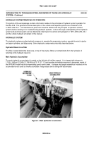
Figure 6. Bowl Area Major Components
Back to Top

