TM-5-2350-378-24-P - Page 31 of 790
TM 5--2350--378--24&P
0004 00--6
INTRODUCTION TO TROUBLESHOOTING AND REPAIR OF THE M9 ACE HYDRAULIC
SYSTEM -- Continued
0004 00
HYDRAULIC SYSTEM -- CONTINUED
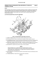
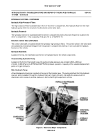
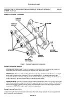
Figure 7. Hydraulic Suspension Components
Hydraulic Suspension Operation
SPRUNG/UNSPRUNG Circuit
The key to the operation of the M9 ACE is its hydropneumatic suspension
system that allows the vehicle to operate in both SPRUNG and UNSPRUNG modes.
SPRUNG Mode
Pressure is delivered through line 9 to bump stops and front actuator fill valves, causing the
bump stops to extend and limit movement of the front roadwheel arms. The actuators become a fixed
suspension with the accumulators acting like shock absorbers for the system, providing a smooth ride up to
30 MPH (48 Km/H). SPRUNG mode is used for road marches and parking.
UNSPRUNG Mode
Pressure is routed through the SPRUNG/UNSPRUNG valve to line 11 and to the actuator
wheel valves, causing bump stops to retract and the suspension system to become variable. The front of the
vehicle can be raised or lowered, and the operator has independent control of the left and right suspension
components. UNSPRUNG mode is used for earthmoving operations.
Sprung/Unsprung Control Valve
Located to the right of the main directional control valve (DCV) bank, facing rearward, this valve regulates fluid
flow for whichever mode is selected.
Back to Top

